This section describes the various 2D objects you can create. See Selecting 2D Locations for details on defining and selecting locations.
The following functions enable you to create lines and objects created from lines, such as rectangles and polygons:
Line – LIN, Ctrl + L |
With this function, you can create a single line, a multi-segmented line, or a freehand curve. While creating lines, the following additional options are available:
| Close - joins the last point and the first point to close the line. |
| Freehand - creates a freehand curve by holding the mouse button. |
| Endpoints – the default mode, in which each mouse click defines a segment endpoint. This option cancels the freehand mode. |
| Separate Objects - creates each line segment as a separate object. |
| One Object - creates one object that contains all the line segments. |
Multi Line - MLL |
A multi-line is a group of parallel lines that acts as one line. Before creating multi lines, you can set parameters such as number of lines, line distance from the center, and rounding.
| Multi Line Attributes - change properties during multi line creation. |
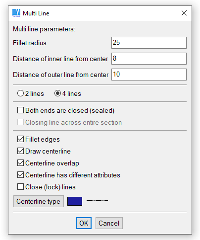
Multiple lines options
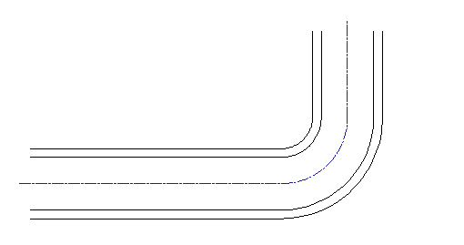
Example of multi lines created within one function
Shaft - SHAFT |
Creates shafts or other symmetrical 2D objects. Before creating shafts, you can define coordinate display, rounding, chamfering or creation of conical or cylindrical parts. When drawing shafts, coordinates are displayed as DX, DY. You can choose whether DX is measured from the first shaft point (total length from beginning) or from the last point (length of the created segment).
| Shaft Attributes - change properties during shaft creation. |
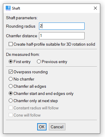
Shaft options
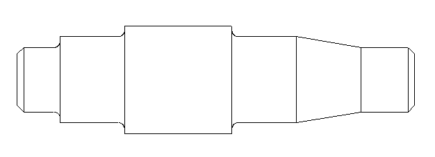
Example of object created by Shaft
Rectangle - RECT |
Creates a rectangle by two opposite corners definition. If you right-click an empty area when a first rectangle or a second rectangle corner is defined, a pop-up menu appears and you may select cursor increment mode or enter exact rectangle dimensions from keyboard.
Polygon - POL |
A polygon is an object in which all sides have the same length. The polygon can fit inside or outside a specified radius, and you can define the number of sides (vertices) and vertex location.
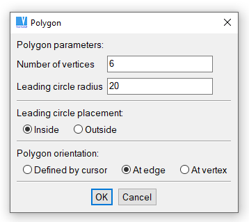
Polygon options
Tangent Line - TAN |
Creates a tangent line by selecting two circles or arcs. The tangent line endpoints are located where you select the circles/arcs.
Arrows - ARR |
An arrow is a single- or multi-segment line that has an arrowhead at the end of its last segment.
Arrow Attributes Setting - ARA |
This function is available on the Tools menu. You can set the following attributes:
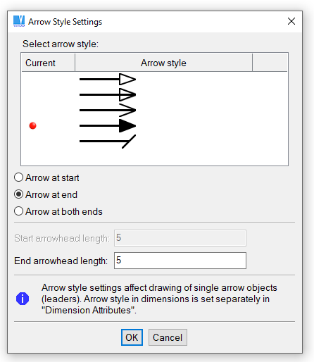
Arrow style settings
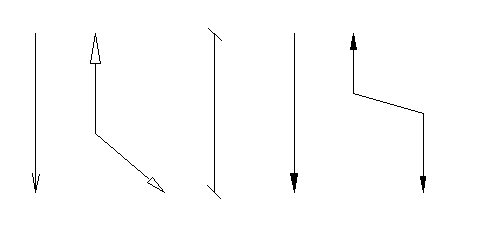
Example of various types of arrows (each arrow is a single object)
2D Objects, XY Coordinates from File – 2DFF |
Various types of 2D objects can be defined by X and Y coordinates loaded from a text file. See image below. After selecting type of 2D objects and other properties, select a file-name. Values are loaded from the file, and you can insert a new 2D object.
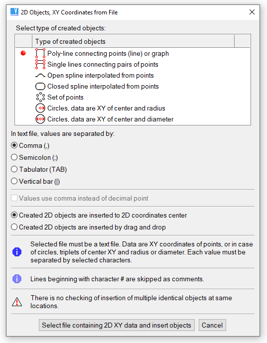
2D Objects, XY Coordinates from File
Ellipse - ELL |
An ellipse can be created by defining major and minor axes, or by projecting a circle. To create an elliptical arc, you can define start and end angles. Identical angles will produce an entire ellipse. You can easily specify identical angles by pressing the Space Bar twice at the same location – first, while entering the first angle and again (without moving the cursor) while entering the second angle.
Ellipsis is created as a NURBS curve.
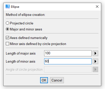
Ellipsis definition
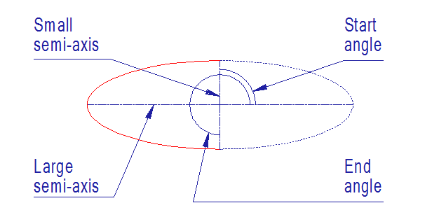
Example of ellipse
Spline - SPL |
A spline is a curve defined by a set of points. The spline passes through the defined points. You can choose whether to create an open or closed spline. Closed curves are connected smoothly – gap between first and last point is spanned.
Splines are created as interpolation NURBS curves.
Points are used in 2D as auxiliary objects.
Point - POINT |
Creates single points by clicking on point locations.
Points on Arc - POC |
Creates points along an arc. You can specify a number of equally-spaced points, or define the distance between points.
Points on Line, Number - PLN |
Creates a specified number of equally-spaced points along a line.
Points on Line, Distance - PLD |
Creates points along a line, separated by a specified distance.
Points from File - PFF |
Inserts points from a text file, listed as X, Y coordinates. Each set of coordinates in the text file must be separated by a space.
Circles and arcs are the same type of 2D object; a circle is a 360 degrees’ arc. Angles of arcs are measured counterclockwise, with zero degrees along the right direction of X axis. If a circle or an arc is defined by cursor dragging, you may press right mouse button. Then, menu appears and you can select cursor dragging increment or define exact radius value from keyboard. In most situations, cursor increment is measured as DX DY from last defined point or from coordinate center. But when you drag a circle or arc from its center, cursor increments are measured as increments of radius.
Circle Center Radius - CCR |
Creates a circle defined by a center point and radius.
Circle Center Point - CCP |
Creates a circle by defining the center point and a point on the circumference.
Circle 2 Points - CR2 |
Creates a circle by defining two circumference points and the radius. The circle is created when you specify the side of the circle center, relative to the line connecting the two circumference points.
Circle 3 Points - C3P |
Creates a circle by defining three circumference points.
Circle Tangent to 2 Objects - CT2 |
Creates a circle tangent to two objects (lines, circles, arcs) with a specified radius.
Circle Tangent to 3 Objects - TG3 |
Creates a circle tangent to three objects (lines, circles, arcs).
Group of Holes - HOL2 |
Creates a group of holes (circles) along a circle or line.
Arc Center Radius - ACR |
Creates an arc by defining the center point, radius, and start and end angles. To create an entire circle, the start and end angles must be identical. You can easily specify identical angles by pressing the Space Bar once while entering the first angle and again (without moving the cursor) while entering the second angle.
Arc Center Point - ACP |
Creates an arc by defining the center point, point on circumference, and start and end angles. To create an entire circle, the start and end angles must be identical. You can easily specify identical angles by pressing the Space Bar once while entering the first angle and again (without moving the cursor) while entering the second angle.
Arc 2 Points - AR2 |
Creates an arc by defining the radius and two endpoints. The arc is created when you specify the side of the arc center, relative to the line connecting the two endpoints.
Arc 3 Points - A3P |
Creates an arc by defining the first endpoint, a point on the circumference, and the second endpoint.
Arc Point Tangent - APT |
Creates an arc by defining the radius, point on circumference, and a tangent line or arc. The arc is created when you specify the side of the arc center.
Arc Tangent to 2 Objects - AT2 |
Creates an arc tangent to two lines or arcs, specifying the arc radius.

|

|

|