Adding solids together and using one solid to cut volume from another are called Boolean operation. These operations can be performed when solids have volume in common (overlap) or have at least one common (or partially common) surface. In addition to Boolean operations described in this section, there are other predefined Boolean operations including drilling holes, milling, creating grooves, filleting and chamfering.
Add Solid – ADD, Ctrl + A |
Combines two solids into one object. First select the solid to be added, and then select the solid to be added to. Although the final result is the same, the selection order can be important. If the solids have properties such as certain attributes or group membership, the final solid will have the properties of the second selected solid - the root solid.
Cut, Delete Cutting Solid – CUT, Ctrl + W |
Uses one solid as a cutting tool to remove volume from another solid. The cutting solid is then deleted. For example, to create a conical hole, use a cone as a cutting tool to remove volume from a cube.
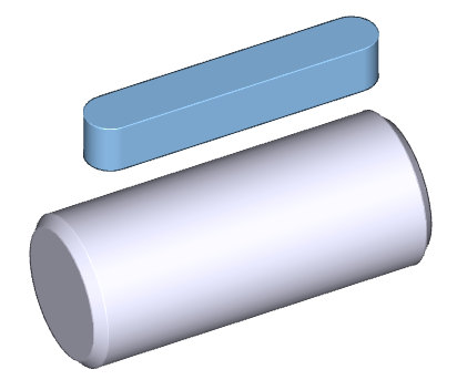
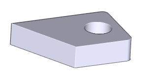
Example of Cut, Delete Cutting Solid. The spline is the cutting tool; the pin is the root solid.
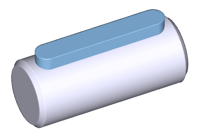
The spline is embedded into the pin.
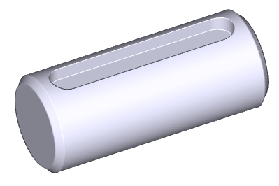
The resulting cut solid. The spline is deleted.
Cut, Keep Cutting Solid - CUTS |
Similar to Cut, Delete Cutting Solid, except that the cutting solid is not deleted.
Selective Add - ADDPC |
Similar to Add, used to add solids that overlap or extend past the root solid. Select the added solid at the section you want to remain; other sections will be trimmed.
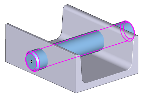
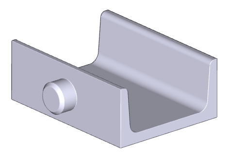
Example of Selective Add. The cylindrical pin is to be added to the U-iron. The pin is selected where indicated.
The resulting added solid. Only the section selected was added, the rest of the solid was trimmed.
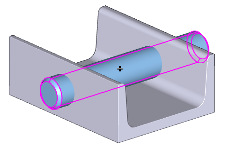
Using the same initial solids, the pin is selected at a different location.
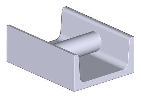
The resulting added solid. The middle section only was added.
Selective Cut, Delete Cutting Solid - CUTPS |
Similar to Cut, Delete Cutting Solid. For the cut solid, only the section you select will remain; other sections will be deleted. The cutting solid is also deleted.
Selective Cut, Keep Cutting Solid - CPSS |
Similar to Selective Cut, Delete Cutting Solid, but the cutting solid is not deleted.
Solid Intersection - SIN |
The result of the solid intersection is a volume common for both selected solids.
Add Solid, Perform No Intersection - NADD |
This command adds a solid into solid tree structure, but performs no Boolean operation. This way, you can create solids from elements which do not intersect or touch each other, or which touch each other only in one point or line. Typical example is creation of a ball bearing. You can add balls to inner ring and then outer ring to the rest.
If solids containing multiple closed volumes (lumps) are exported into STEP, they are divided into multiple single solids.
Mechanical parts inserted from libraries (like screws, pins, rings and others) allow you to modify a counterpart. See Modifying Counter-parts, Drilling Holes for Screws in section Libraries of Mechanical Parts.
Boolean Tree Structure Editing – TREE |
You can change the Boolean structure of a selected solid. It is possible to change an order of Boolean tree branches or to copy or move out Boolean tree branches. Each branch can be selected in Boolean tree scheme or can be detected interactively in 3D space.
Copy Tree Branches Select if the Boolean tree branch will be copied out of the solid or moved out of the solid. Then select a branch and locate it into 3D space. Location works with the same tools as insertion of new solids or as transformation of solids - see Transforming and Copying Solids. Lone blending cannot be selected. |
Edit Tree Structure Select a Boolean tree branch and then a branch the previously selected object will be moved after (or optionally, in front of). You can move at the same level or to a higher level. Each time the Boolean tree is rebuild, the order of performed operations is from up to down as displayed in scheme. If you change the order of operations, you can obtain a different shape of the solid. Another benefit may be that you can easily remove or copy out branches. Also, filleting or chamfering can create different results. |
The Boolean tree scheme window is displayed at second monitor, if VariCAD works at two monitors. Following examples show possibilities of editing solids, using Boolean tree scheme.
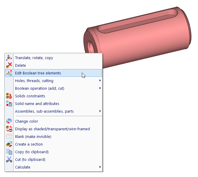
Right click a solid, then select “Edit Boolean tree elements”.
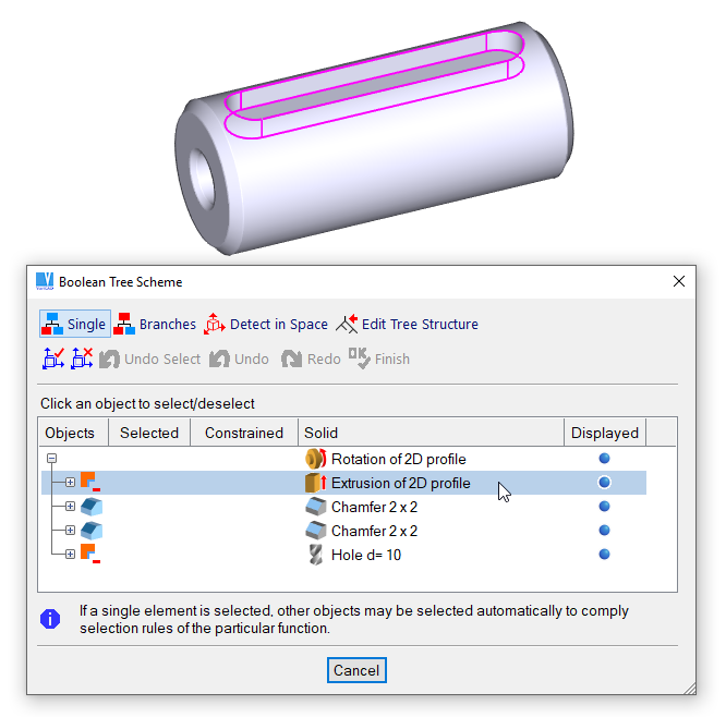
When you move cursor over the elements in the schema, corresponding 3D objects are highlighted.
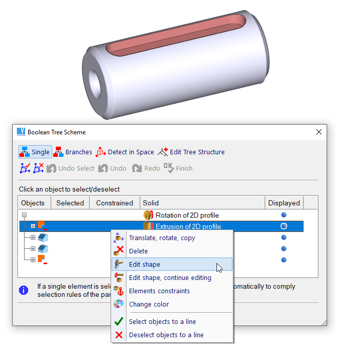
Right-click a line and then select a command from menu
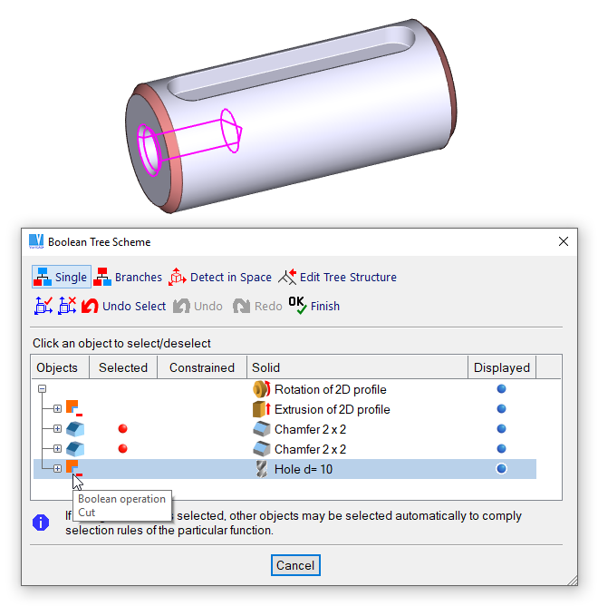
A group of elements can be selected by left-click, then processed after right-click. This example also shows tool-tip under cursor hovering above an icon.
Hole, Mill, and Groove all use a cutting tool to remove volume. The dimensions of the cutting tools are specified similarly as for basic 3D elements; you can also copy dimensions from another object. For example, in the Hole function, you can copy the dimensions of an existing hole.
You can select these cutting commands from tool-bar or also, if you right-click a solid and then, from pop-up menu. After the command is selected, you have to define dimensions of a cutting tool in a table. Then, the tool is inserted into space. You can redefine dimensions the same way as if you create a new solid – see Editing of Spatial Dimensions of Basic Solids.
The tool is pre-inserted according to a solid’s surface – it means where you clicked the solid to be cut (or to be drilled, for instance), there is the tool inserted. Also, the tool is properly oriented according to normal of the surface. Next, define the final tool location.
If you drill a hole and if you click an existing hole drilled into a solid, the drilling tool is positioned exactly as the tool which created the detected hole.
Hole - HOL |
Drill holes into objects. You can optionally create recesses, or use a chamfered or tapered bottom.
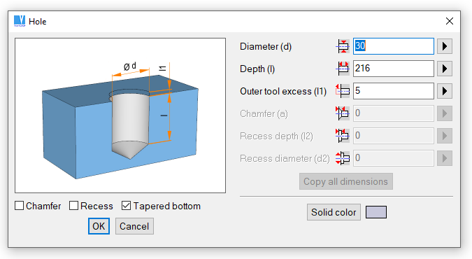
Definition of a new hole
Groove - GRV |
Removes volume by using a spline tool.
Cut by a Box (Milling) - MIL |
Removes volume by using a box as the cutting tool. If the box dimensions are large enough, you can, in effect, cut by plane. We recommend to use rather command “MILX”, see below.
Cut by an Extruded Solid - MILX |
Select a sketching plane and create a contour of the cutting tool. After confirmation of contour shape and location, the tool is created and automatically cut from the solid.
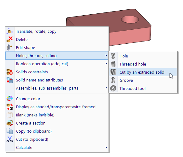
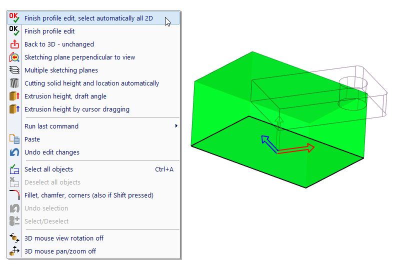
After right-click the upper plane, a pop-up appears. Select cutting by an extruded solid.
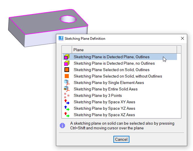
Select a sketching plane.
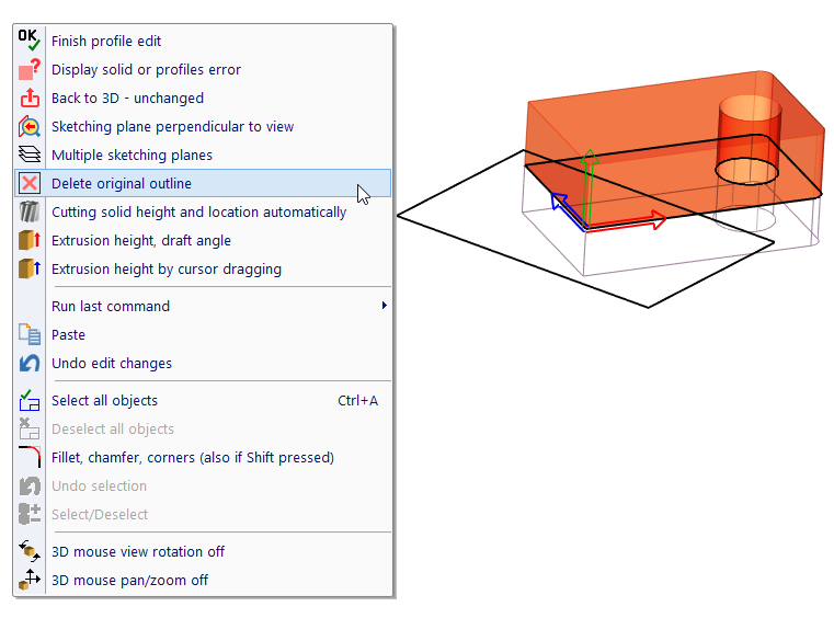
Create a contour of the cutting tool. Original outline still remains, remove it by option as displayed here.
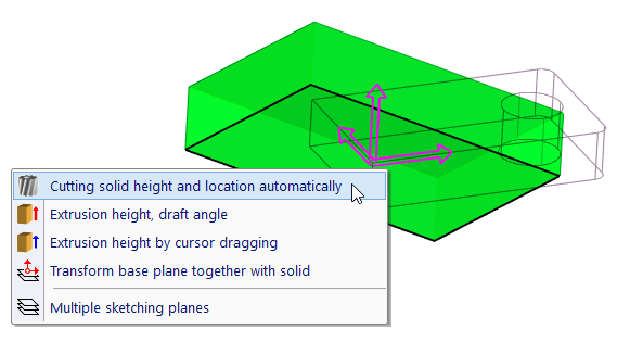
After removing extra lines, you can define height and location of cutting tool automatically. Click the axes, or right-click an empty location and select automatic definition from menu.
The tool created by sketching, before final confirmation.
After confirmation, the tool is located and cut from the solid at one step.
Other commands cutting material are those creating threads – see Threads in 3D
If you define hole or groove dimensions, images in panel are changed according to selected option. Also, you can define dimensions by spatial dimensioning similarly as for basic volumes – see Basic Solid Volumes.
Explode Boolean Tree - TRX |
Resolves a selected solid into its basic parts. Solids used for adding or cutting are changed back to their original objects. It is not recommended to use this function, if you only want to remove parts of Boolean tree (like holes or fillets) or if you want to change position of parts of Boolean tree relatively to other parts.
When using these blending functions, first select the edges to be filleted (rounded) or chamfered. Then specify the fillet radius or chamfer distance. Rounded or chamfered edges are kept if the solid changes during editing. The Fillet function handles fillet overhangs and undercuts in most cases.
| Select Continuous Edge – this is the default option. One or multiple edges are detected by cursor, if they are all connected tangentially. |
| Select Single edge – each edge must be detected and selected individually. |
| Select Patch Outline – patch outline edges are detected. |
You can select multiple edges. Edges may not be continuous, but they all must be from the same solid.
To detect edges between commands, press and hold Shift and move the cursor. You can also choose edges selection from pop-up menu, if you click an empty area and if you don’t have already selected solids.
For filleting, you can select optionally:
3D Fillet - RN3, Ctrl + F |
3D Chamfer - CH3, Ctrl + R |
For chamfering, you can define a chamfer distance different for each side of the chamfered edge. If you select an edge of a threaded surface (for instance, end of screw or edge of threaded hole), optionally, the chamfer distance may correspond to the respective thread.
Delete Solids – RMS, Ctrl + D |
Deletes selected solids. You can select entire solids as well as their components. For example, you can use this function to delete holes, fillets, ribs, etc. If such parts are selected, the solid will be regenerated, which may take time for complex objects.
Edit Solid - MSO |
This function allows you to:
Method of solid’s shape editing is selected from toolbar:
| Icon | Key | Use |
| N/A | Edit shape of basic solids or blending | |
| N/A | Transform elements within solid | |
| N/A | Translate basic solids according to previously changed dimensions | |
| N/A | Change diameter of pipe or wire | |
| N/A | Change thickness of shell | |
| N/A | Shell pattern edit | |
| Enter | Finish selection of elements to be edited | |
| N/A | Undo edit change | |
| Enter | Finish editing | |
| N/A | Skip editing and set creation properties | |
| N/A | Back to 3D, unchanged |
The Enter key (finish) is available either for “finish selection” or for “finish editing”.
Select a basic solid to be edited. After selecting the first object, you can select more same basic elements from solid. Then confirm selection. If multiple objects were selected, shape change is performed for all of them at once. For instance, you can change several holes, fillets or any same elements together. Following objects are considered as the same elements:
For instance, if the first selected object is a box, then other selected objects can be only boxes until the selection is finished. If the first object is a fillet, then next can be only fillets, etc. To distinguish how an object will be edited, the cursor is changed according a type of the object.
Cursor types:
| Cursor | Use |
 | Object cannot be selected – object belongs to different solid than first selected object or object is different than first solid |
 | Spatial dimensions will be used for object’s shape modification |
 | Object is fillet |
 | Object is chamfer |
 | 2D creation profile will be edited |
 | Object is shell; thickness will be changed |
 | Object is pipe or wire; diameter(s) will be changed. |
 | Object cannot be changed. Object is imported from STEP. |
 | Object cannot be changed. Object is in active section. |
 | Shell shape editing, spatial dimensions will be used. |
 | Shell shape editing, fillet radius will be changed. |
 | Shell shape editing, chamfer distance will be changed. |
 | Shell shape editing, 2D creation profile will be edited. |
 | Shell shape editing, element cannot be changed – object is different than first selected object or object is imported from STEP |
 | Pipe segment editing, shape of straight segment or elbow will be changed. |
As a basic solid, you can select solids used in Boolean operations - a solid added to another solid, or a cutting solid used to remove volume from another solid. As a basic solid, you cannot select any object imported from STEP. If the solid to be edited was created from a 2D profile, such as an Extrude or Revolve, you can edit the 2D profile. If the cursor passes over such an object during solid selection and the object is highlighted, the creating profile is also displayed. Together with this profile, its axes are displayed, too. This allows you easy orientation while editing the profile. After selecting the solid, the system switches to 2D drawing in 3D, and 2D editing functions are available. The profile is displayed with its original X and Y axes. When the editing is completed, click the icon on the Edit 2D Profile toolbar. Then reselect the profile’s 2D objects. See also Defining a 2D Profile. When editing 2D creation profile, you can leave the task only by clicking any icon in 2D Edit toolbar. This toolbar offers you to:
Predefined solids (box, cylinder, pipe, etc.) or results of predefined Boolean operations (hole, etc.) can be comfortably edited using spatial dimensioning. Optionally, you can select solid’s dimensions in the table (window). Such an option allows you to change also shapes, like add a recess to a hole. See also Editing of Spatial Dimensions of Basic Solids.
For more information, related to editing of solids’ profiles, see Creating 3D Solids from 2D Profiles or Rotating, Extruding, and Lofting Profiles.
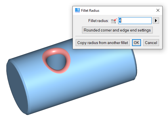
Example of fillet editing
After specifying changes, the entire solid is regenerated. It is possible that editing will cause a situation in which the solid cannot be regenerated. Example: a 10mm hole is drilled into a cube with side 20mm. If the diameter of the hole is changed to 50mm, the solid cannot be regenerated. In cases like these, you will receive an error message, and the Boolean tree remains unchanged.
See Transforming and Copying Solids for more details how to change object’s location. For changing the object’s location within entire solid, you can select object of any type (unlike the selection for shape editing), except the blending.
This option is available only if the translation distance and direction can be exactly determined. For instance, if you change height of a box, you can translate any other objects in direction of Z-axis of the box at a distance predefined as a difference of the previous and new height. Thus, you can easily preserve position of any objects relative to changed side of the box.
If the option is available, an arrow in a respective direction is displayed. You can select objects to be translated and then click arrow or icon. You can also click the icon first and then select objects to be translated.
If you need only to change the solid element’s location use Transforming and Copying Solids instead.
Shell is created as offset patches connected to selected patches at a given thickness. You can change:
Selecting elements for a shape change, the cursor type is changed differently than for other ordinary solids - see Cursor types.
The shape of the pattern can be changed separately. You may extract a copy of the pattern solid back into 3D space. Then, you may perform any editing functions. After the all changes, select again the corresponding shell for pattern editing. Confirm, add or remove patches. The shell will be rebuilt. This method allows you to rebuild the shell, if you need:
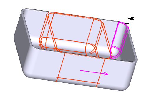
Example of the shell editing
Pipes or wires are created as a set of cylindrical segments and elbows.
You can change:

|
|

|