Geometric constraints can be defined among solid elements inside a Boolean tree, or among entire solids in 3D space.
If constraints are defined inside a Boolean tree (inside a solid created from multiple elements), they allow you to fix a position of a particular element. Whenever a shape of the solid is changed, the position of constrained elements is redefined according to a new shape. Such definition of constraints is very convenient – without them, you must often perform additional transformations of the element. Sometimes, it may not be possible.
If constraints are defined among entire solids, a position of a constrained solid or solids is changed, whenever a shape or location of related solid is changed.
In essence, constraints are based at:
Both aspects describe how constraints work, but from different angle of view.
Additional transformations are performed according to a constraint type, see Available Types of Geometric Constraints. For instance: Define a constraint fixing an object at a distance from a patch and in direction of Y axis. Then, an intersection of Y axis and the patch is calculated. The constrained object is kept at a given distance, measured along the Y axis.
Additional transformation is performed:
After some changes, one or more constraints may not be performed. In the example above, it may happen if the patch is a plane and if the Y axis is parallel with the plane, after objects transformation. In such case, the constraint is ignored.
Each object in 3D space has six degrees of freedom. Three of them are rotations – around X axis, Y axis and Z axis. Three of them are movements – along X axis, Y axis and Z axis. If an object is constrained, one or several degrees of freedom are removed. For instance, object is fixed at intersection of Y axis with a selected path – removed degree of freedom is movement along Y axis.
If you fix rotation around two axes, the result is, in fact, fixed direction of the remaining axis. For instance, some constraints fix direction along a normal of a selected plane. Consequently, this constraint fixes rotation around remaining two axes.
Fixed movements, rotations or directions of axes are displayed either in constraint panel or in various dialogues – see below. And mainly, fixed movement or rotation is shown at a corresponding axis – as a short line across the tip of the axis.
Constraints may be defined:
Constraints cannot be defined:
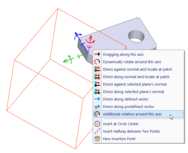
To define a constraint, click the inner part of corresponding object’s axes. Optionally, you may click an icon in the Constraint panel. To edit a constraint, click the outer part of an axis. Then you may select:
You may work with constraints within a function transforming solids or their elements, see Additional Boolean Operation, Constraints Definition. The constraints can be created or edited after the location is defined. Another option is to skip a location definition:
Create, Change or Remove Geometric Constraints among Solid Elements, CST |
Create, Change or Remove Geometric Constraints among Entire Solids, CSTS |
These functions work with constraints without necessity to define a location. It is possible to define constraints either for solid elements within one solid, or among entire solids in 3D space. Both functions work identically.
Either for the function “Solid Transformation” or “Geometric Constraints”, transformations necessary for a particular constraint are always performed. It is more convenient to define a location and then to switch to constraints definition than to define a location only within the constraint definition. Transformation possibilities within the constraint definition are limited.
To create, change or delete constraints, you can right-click an object and select the command from pop-up menu. In case of constraints of a solid element, press and hold Ctrl and move cursor over objects. Then, single elements are detected and menu called by right-click is related to detected element.
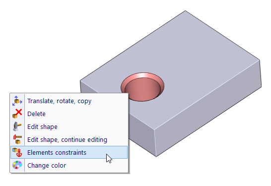
Selecting constraint definition from pop-up, for a detected element (hole)
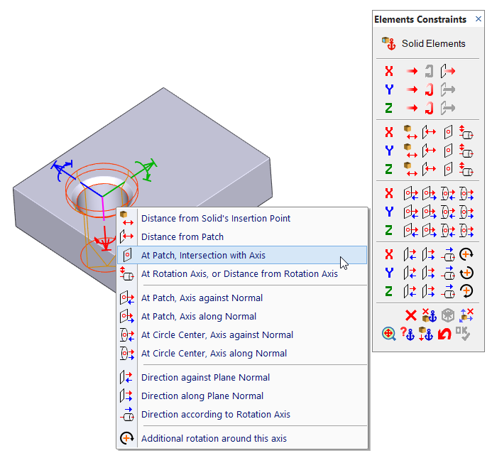
Constraint definition, Constraint panel
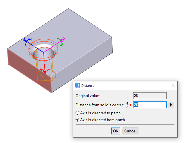
Constraint definition, example of constraint fixing a distance to selected patch
Constraints fix a constrained object in its movement along an axis or in rotation around the axis. The constraining is performed for the insertion point of the object. You may change a location of the insertion point until constraints are defined. Then you may change the location of the insertion point only temporarily within the current function. The change is not accepted permanently.
Also, you cannot change permanently a location of the insertion point, if the corresponding element is an anchor for another constrained object and this object is constrained right to the insertion point.
| This option, which is available for objects selection, allows you to select an entire constrained group of solid elements. |
| Similar as previous, allows you to select an entire group of constrained solids. |
If you select objects for transformation, the complete constrained group is detected. You cannot change a location of a single element of the constrained group individually.
Automatic detection of a constrained object is displayed at the cursor:
| Cursor | Use |
 | A constrained group or constrained object is detected |
 | The already constrained object cannot be selected for the current constraint definition |
| This option, which is also available for objects selection, allows you to select either constrained group of objects or to select objects the group is constrained to. |
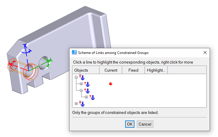
Constrained objects are displayed in the scheme. Such a scheme shows you legibly all dependencies – you can see the entire chain of constraints. Before selection, you can optionally highlight a constrained group – so you can see exactly which object or objects will be selected. Also, you can optionally click an object in 3D space and if constrained, it is highlighted both in the scheme and in 3D.
If you want to select anchors (or master solids, or solids the group is constrained to), click a corresponding column in the scheme. Then you can highlight each constraint individually – again because you will see which object will be selected. Or you can select the anchor of each constraint.
Generally, a group (often containing only one object) can be constrained to multiple different objects.
You may select multiple objects for constraining. The insertion point is the point of the first selected object. If you need to add a new object into a constrained group, select the group and a new object (or multiple new objects). They are added automatically.
| This option, which is available in the Constraint panel, allows you to remove an object from the constrained group. |
| This option displays scheme of all constraints, so you can see the currently defined constraints in relation to other constrained objects. |
| Allows you to work conveniently with all constraints currently defined for the selected object (objects). |
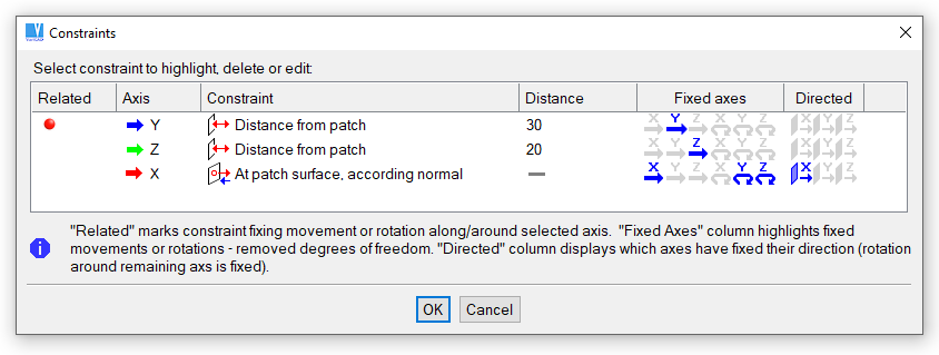
Dialog panel containing a list of currently defined constraints
| This option, which is available in the Constraint panel, cancels all constraints of the currently defined group. |
All constraints are related to a specified axis. Direction of the axis may be selected along or against to a normal or another axis in dependence on a particular situation.
Definition of a constraint rewrites all existing constraints whose fix any axis of the object the same way as the new constraint. Fixed movements, fixed rotations or defined directions for the constrained object are displayed in the upper part of the Constraint panel.
If any of existing constraints has to be removed by redefinition, a dialogue panel is displayed and you can confirm such change.
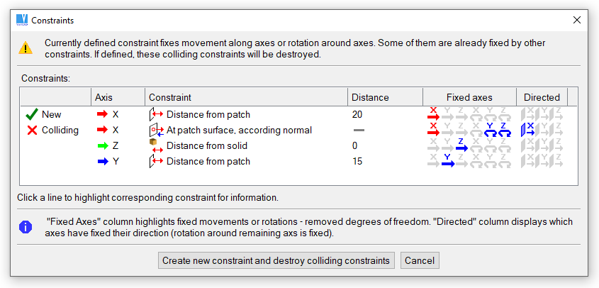
Example of a new constraint colliding with existing ones
| Distance to solid's insertion point. Constrained object is at a defined distance from the insertion point of a selected object (another solid element). Distance may be either positive or negative (along or against the axis arrow), or zero. This type of the constraint is often used for definition of a distance between holes or other solid elements. |
| Distance from a patch, the axis is not directed. Intersection between the axis and the selected patch is calculated. The constrained object is fixed at a specified distance from the intersection. |
| Location at a patch, the axis is not directed. This constraint is similar to the previous, but the distance is always zero. |
| Location at a patch, the axis is directed according to a normal. The nearest point at a patch is found. Then the object is moved to the nearest point and the corresponding axis is directed against or along the normal of the patch at the location. This type of the constraint fixes the object at a surface and adjusts always its orientation. It can be used often for location of a hole – the object is always at the surface and the axis is always oriented perpendicularly to the surface. |
| Location at a circle center, the axis is directed according to the normal of a planar surface. This constraint is especially useful for joining pipe or shaft segments. |
| The axis is directed according to a plane normal. This constraint is performed always as first before the other constraints. It defines orientation of the constrained object. Only one axis can be oriented this way. |
| The axis is directed according to a rotation axis. The axis is parallel to the axis of the rotation surface. |
| Object is constrained at a distance from a rotation axis. An axis selected from the remaining two axes is simultaneously directed according to the rotation axis. |
Clicking an outer part of object’s axes, you may select deletion of the corresponding constraint (see above). If you need to cancel the constraining of a selected axis, use following options:
| Constraint fixing movement along the axis is deleted. |
| Constraint fixing rotation around the axis is deleted. |
| Constraint fixing alignment of the axis is deleted. |
Constraints within a solid cannot be defined without a limitation. Basically, if an object A is constrained to an object B, then the object B cannot be constrained to the object A. All objects can be constrained to an object which is not constrained further.
If the object A is constrained to the object B (for instance, fixed at a distance from a patch of the object B), and the object B is constrained to the object C, a sequence of objects A, B and C creates a constrained chain.
Regarding the already existing constraints, you cannot anchor a constrained group at an object, if:
System automatically blocks the selection of anchors, if the constraint is not possible. The cursor is automatically changed at such a situation (see Selecting Constrained Objects
Chain of constraints
When the position of constrained elements is redefined according to a new shape, it may be moved inconveniently. For instance, you may define a chain of constraints within a shaft. After changing a length of a segment, all remaining segments are moved. You may want objects to be moved in opposite direction. You can fix a selected element from the entire solid. Then the element remains always in the same position – it is not translated or rotated. If no element is fixed, then elements without constraints remain at the same location.
| This option, which is available in the Constraint panel, allows you to fix a selected element to the current location. |
To constrain an angle, perform an additional rotation around an axis first.
See Additional rotation around an axis. As angular value, enter or define a new parameter. Then constrain selected objects, if they are not already constrained.
It is necessary to fix direction of at least one of remaining two axes. For instance, the example displayed below constraints angle of rotation around X axis. Here, you should fix direction of Y or Z axis. Preferably, fix a direction of one of these axes along a normal of planar surface.
If you change the corresponding angular parameter, the angle is recalculated and constrained objects are rotated according to the new angle. The necessary condition for fixing angles by parameters is that the objects must be already constrained at least once. Direction of any perpendicular axis must be fixed. Otherwise, after a change of the angle the axes are rotated instead of the objects.
Another advantage of additional rotation around axes combined with constraint definitions is a possibility to constrain objects in any direction, regardless of the initial state of their axes. Objects are always constrained in direction of X, Y or Z axis. The axes are directed according to how a solid was created, and the direction may not be always convenient. After transformation of objects and additional rotation around an axis, you may constraint objects exactly in desired direction.
Additional rotation around X-axis

|
|

|