Full Rotation - RSO |
Rotates one open or closed profile 360 degrees around a rotation axis. The rotation axis is the X axis of the base sketching plane.
If a profile is selected in 2D mode, you must define the axis. For an open profile, the axis is connection of the profile endpoints. For a closed profile, you must define the axis by two points. If the insertion point is defined automatically (according to configuration), it is located at the first defined point of the revolving axis. When selecting closed profiles, multiple profiles are allowed inside one outer profile - this will create holes in the solid.
Example of Full rotation of 2D open profile
Partial Rotation - RSOP |
Similar to Full Rotation, except that you can enter angle less than 360 degrees. During sketching, you can define the angle by cursor movement.
Example of partial rotation using closed profiles
Extrude - ESO |
Command extrudes a profile to specified height, forming a solid. Profiles must be closed and multiple profiles are allowed inside the outer profile - this will create holes in the solid. Optionally, you can select a draft angle of extrusion.
You can define extrusion height by cursor movement during sketching. The height can be both positive - the solid is created above the sketching plane, in direction of Z axis, or negative. Then, the solid is created under the sketching plane.
It is convenient to use cursor movement in increments. To define increment, or to turn this option on or off, right-click when you change extrusion height or rotation angle by cursor.
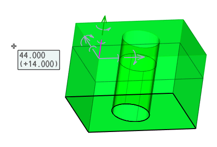
Definition of extrusion height by cursor movement.
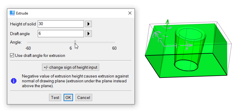
Draft angle defined by cursor movement
Lofting, Multiple Profiles Lofting - MPL |
Lofted solids are created by connection of two or multiple profiles. Each profile is defined at its own sketching plane. Each profile must contain the same number of segments (like lines, arcs, circles or NURBS curves). Unlike extruded profiles, lofted profiles may contain only one inner (inserted) profile.
You can connect one rectangular profile (also with rounded corners) with one circular profile. The connection is done automatically. Contrary to this, if you want to connect multiple profiles in combination like multiple rectangles vs. circles, circles vs. ellipsis or closed NURBs cure, you must divide the circles or curves to the same number of segments.
Loft between Two Planes' Outlines – LB2P |
This type of lofting connects two planes selected at two different solids. After first plane selection, sketching mode is activated and a second plane is selected. Then, you can continue with sketching or you can finish solid creation, if planes can be correctly connected.
Rotate and Loft between Two Planes – MPLR |
This command combines lofting between two planes and rotation around an axis. If a first plane is selected at a solid, the rotation axis is defined as X axis of sketching plane. You may need to redefine the rotation axis and redefine the rotation angle.
For more information, related to multiple sketching plane, see Multiple Sketching Planes
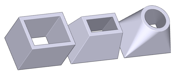
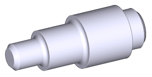
Example of extrude, prismatic loft and loft rectangle to circle
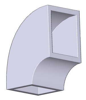
Example of solid coil, created by lofting and rotating profiles
Helix - HLX |
Creates a solid by extruding and rotating a 2D closed profile. You can choose whether the profiles represent the radial, normal or axial section. For example, a spring uses a circle as the normal section. Using a negative rotation angle creates a helix with left ascent.
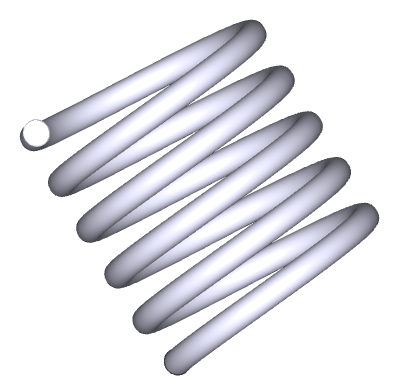
Example of spring helix defined by a normal section
Basic solids are easy to create; you need to specify only basic dimensions. Editing involves changing the basic dimensions, or modifying any 2D profiles that are used. When entering solid dimensions, you have the option of copying any or all dimensions from another solid of the same type. Primarily, dimensions of solids are edited using spatial dimensioning. Optionally, you can select entering dimensions in panel. In panel, you can also change basic shape, like chamfering cylinders etc.
Corresponding images displayed in panels are changed according to currently set options. For instance, a cylinder options allow you to select chamfers or radii. Changing these options, images are displayed with/without chamfers etc.
When a basic volume is inserted and you select one step back (Ctrl + Z, or undo mouse button), the basic volume is displayed together with spatial dimensions and you can change dimensions by editing these dimensions.
The basic solids are as follows:
Box - PRS |
Cylinder - CYL |
(with option of rounding or chamfering either end)
Cone - CON |
Pyramid - TPY |
(uses rectangular base)
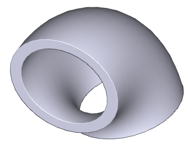
Pipe Elbow - PEL |
Pipe - PIP |
Cone Pipe - CPI |
Solid Elbow - ELW |
Sphere - SPH |
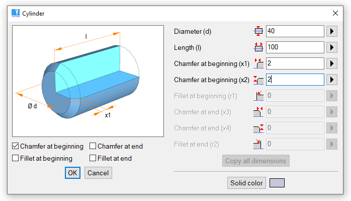
Example of definition of cylinder’s dimensions and shape
If you create a new solid, first define dimensions in a table. Then, a new solid is located. You can right-click it and select redefinition of dimensions, by spatial dimensioning or in a table.
Spatial dimensions are used as a first option, if you select a solid for editing. To change the selected dimension, click it and rewrite value in a dialog window.
You may click a witness line or an arrow of the dimension. Then, you may drag the dimension by cursor movement. Together with it, the shape of entire solid is changed. Some situations even permit to change the dimension in direction of the selected arrow, or symmetrically.
It is convenient to use cursor movement in increments. To define increment, or to turn this option on or off, right-click when you modify dimension by cursor movement.
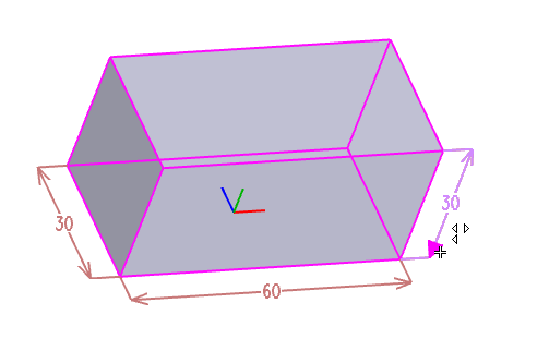
Selecting a dimension to be edited. Here, multiple options are allowed.
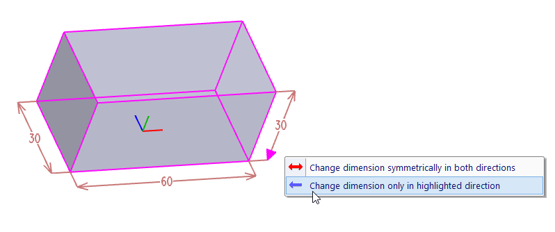
Selecting direction of dimension change. This option is a default option and can be selected by single click at the arrow.
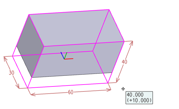
Changing the selected dimension by cursor movement.

|

|

|