Dimensioning enables you to describe geometry by displaying measurements. All dimensioning functions can be found on the Dimensioning toolbar or in the Objects / Draw menu. To create dimensions, select the objects to measure and drag the mouse to locate the dimension text (see Dragging Objects ). Dimensioning tools have several options for additional formatting and settings.
If dimensions are created in 3D views exported into 2D area, connections between dimensions and corresponding 3D objects are established. After changing 3D geometry and returning back into 2D mode, dimensions are automatically updated. See Automatic updates of dimensions, axes and hatches after changes in 3D
Once created, the dimensions can be easily edited (see Editing Dimensions ). Format and style of dimensions and dimension text can be modified using Dimension Attributes. Changing dimension text height affects the length of leader lines arrows.
Horizontal Dimension - HDI |
Vertical Dimension - VDI |
Diagonal Dimension - SDI |
Single dimensions are defined by selecting start and end points, then locating the dimension text.
| Change Dimension Shape - Before the text location is defined, you can change the current dimension format. You can also use Dimension Format to set the format of future dimensions. |
Dimension Format provides the following options:
These options of Dimension Format allow you to define the level (text location and dimensioning line location) of created dimension or all future dimensions:
The last option from menu allows you to redefine the dimension style.
Dimension arrows changed
| Change Dimensioning Scale |
Dimension scale value multiplies measured values of linear, diameter or radius dimensions. It must be used, if a part of 2D drawing is created in different drawing scale than entire drawing (for instance, in case of enlarged details).
| Change Text or Tolerance - modify the dimension text or tolerances. |
Dimension text is created automatically, and you can use Dimension Attributes to define its parameters. For currently created dimension, you can change text in the text input window.
You can select this option by clicking the corresponding icon in toolbar, from pop-up menu (available by default after Ctrl + Right-click), or, very conveniently by pressing TAB during dimension text location. The last possibility allows you to easily select the input text field, if you press TAB repeatedly – input is changed from dimension text to upper, then lower tolerance.
Dimension text window offers you to enter special characters, by clicking the corresponding icons. Also, you can click parentheses icon – then, entire text is closed into parentheses. Dimension text is properly updated after changes and remains closed in parentheses, too.
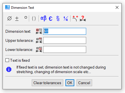
Change dimension text window
Predefined dimensions contain standard text characters such as diameter symbols. These are useful when dimensioning objects like circles or threads.
Horizontal Diameter Dimension - HDM |
Vertical Diameter Dimension - VDM |
Diagonal Diameter Dimension - SDM |
Horizontal Thread Dimension - HTH |
Vertical Thread Dimension - VTH |
Diagonal Thread Dimension - STH |
Example of predefined dimensions
These functions create multiple dimensions. The first dimension in this group is defined as for single dimensions (by 2 points), and subsequent dimensions in the group require only one point.
Parallel dimensions are a group of dimensions that all start at the same point. The offset between parallel dimensions is defined in Dimension Attributes. Datum dimensions consist of a line of points, at each of which the dimension defines the total distance from the start point. Serial dimensions are a chain of aligned dimensions that define the distance from point to point.
Horizontal Parallel Dimensions - HPD |
Horizontal Serial Dimensions - HSD |
Horizontal Datum Dimensions - HDD |
Vertical Parallel Dimensions - VPD |
Vertical Serial Dimensions - VSD |
Vertical Datum Dimensions - VDD |
Diagonal Parallel Dimensions - SPD |
Diagonal Serial Dimensions - SSD |
Diagonal Datum Dimensions - SDD |
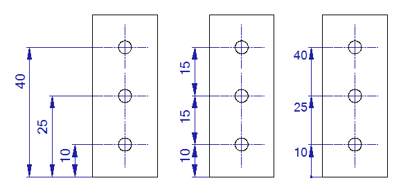
Example of baseline, serial and datum dimensions
Angular Dimension - ADI |
Angular dimensions define the angle between two lines. You have the same additional options for dimension shape changes as for the linear dimensions. See Change Dimension Shape.
For angular dimension, define first and second line. When the second line is defined, you can optionally select following:
| Greater Than 180 - dimensions the angle greater than 180 degrees. |
| Turn off dimensioning of angle greater than 180 degrees, cancels the previous mode. |
| Complementary Angle On - dimensions the angle complementary to 180 degrees. |
| Complementary Angle Off - turns off the complementary angle dimensioning, cancels the previous mode. |
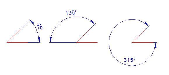
Example of default angular dimensioning, complementary angle dimensioning and dimensioning of angle greater than 180 degrees
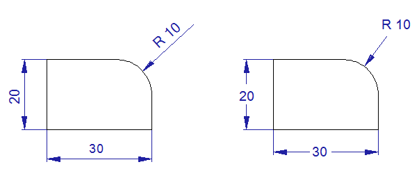
Radius Dimension - RDI |
Diameter Dimension - DDI |
These dimensions are defined by selecting an arc or circle and locating the dimension text. Additional options for radius dimensions are:
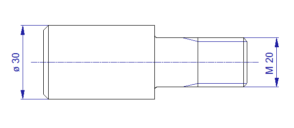
Thread dimensions - THR |
Horizontal Thread Dimension - HTH |
Vertical Thread Dimension - VTH |
Diagonal Thread Dimension - STH |
Thread dimensions behave like diameter or linear dimensions, except the predefined thread symbol is used. If the thread is created in 3D and then exported into 2D, either in sections or in a view, the dimension text is created automatically according to corresponding 3D object. Dimension recognizes thread type (like Metric thread, Pipe thread), and thread size or pitch (like M10, M10x1 …). It is necessary to use these four dimensioning commands to obtain the corresponding thread text, according to creation in 3D. Also, threads should be exported to 2D from basic views (like front view, back view, top view…).
Single Text Arrow - STXA |
Creates a text connected to a single arrow.
Multiple Text Arrow - MTXA |
Creates multiple lines of horizontal text connected to an arrow.
Example of text connected to an arrow
Dimension Attributes - DMA |
Available on the Tools menu, Dimension Attributes enables you to change dimension styles and other properties. The following properties can be modified:
Changing dimension attributes allows you to set dimensioning according to various drawing standards, like DIN or ANSI. Dimension attributes are used also for finish symbols or single or multiple text arrows.
Edit Style of Selected Dimensions - EDS |
This command changes the style of selected dimension or dimensions (also from entire drawing) to a style of a selected dimension, or according to current dimension style settings.
Dimension style settings
Example of dimension styles
Finish Symbols - FSY |
Finish symbols are created by entering a roughness value, or by selecting a symbol for not-machined surfaces. Symbols can be attached to a line, arc or dimension witness line, or they can float. When attaching to a 2D object, you can drag the symbol around the object before selecting its final position.
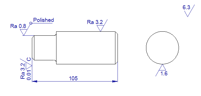
Finish symbols example
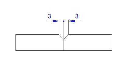
Weld Symbols - WSY |
The weld symbol includes a basic symbol, supplementary symbol, dimension of weld size, and weld process symbol. When defining a symbol, you can change text and other attributes, and see a preview before creating it. You can also save up to nine symbols for future use. To create a weld symbol, first select the weld location and then select the symbol location.
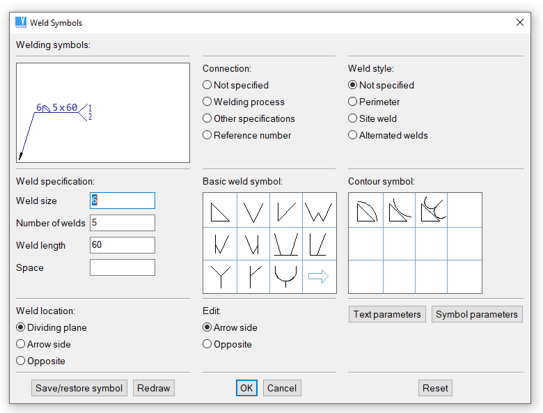
Welding symbols definition
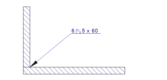
Example of welding symbol; this symbol was created within one function.
Weld Symbol Settings - SWS |
Available on the Tools menu, allows you to choose whether the weld symbols will be created according to ISO or ANSI standards.
Tolerance Symbols - TSY |
Similar to welding symbols. Datum feature symbols can also be created.
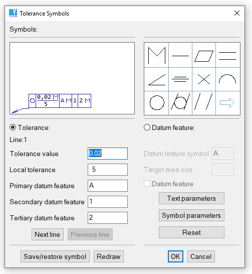
Tolerance symbols definition
VariCAD has a complex system solving item numbers and their appearance in 2D leaders. If BOM mask contains an attribute prototype of type “Item Number”, you can define item numbers of solids together with other solid attributes. Moreover, you can define item numbers in BOM. Here, you may define item numbers for a batch of objects, or for entire assembly at one step. Also, you can remove item numbers the same way. See Defining Item Numbers in BOM section for more information.
If once defined, item numbers are exported to 2D drawings together with corresponding 2D views of 3D solids. In 2D, during leader creation item numbers are detected automatically from 2D objects.
If you change item numbers in 3D solids and if you perform a new export of 3D views into 2D area, item numbers can be checked and updated automatically. If necessary, leaders can be easily deleted from entire 2D drawing or from a selected 2D region. Leaders can be selected as a sub-type of dimension.
Leader style in 2D can be modified as well as a style of dimensions. Leader style settings are part of dimension settings. Leaders themselves are sub-part of dimensions objects.
Create Leaders - LDR |
This command creates 2D leaders. If 2D drawing was exported from 3D and if 3D solids have defined item numbers, leader texts (numbers) are assigned automatically to each leader. Otherwise, the leader number is assigned from 1 and each next leader has the number increased.
Following options are available during leader definitions:
| Changes default text of the created leader. |
| Changes leader (or dimension) style. |
| Sets distance between adjacent leaders. |
| Creates temporary leading lines at the selected leader. This allows you to keep the next leader adjusted horizontally or vertically according the selected leader. |
| Leader witness line is a spline. This switches witness line creation from a single line to a spline. |
| Leader witness line is a single line. It turns off witness line created as a spline. |
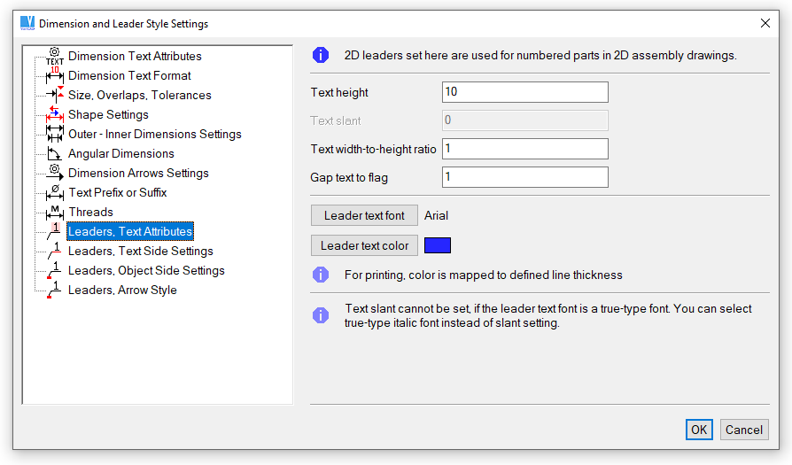
Leader style definition, text style
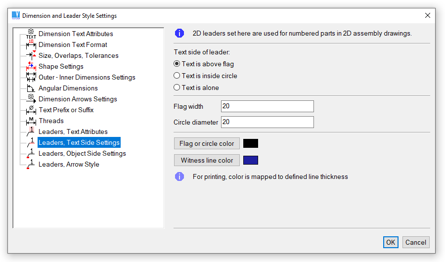
Leader style definition, text side of leader
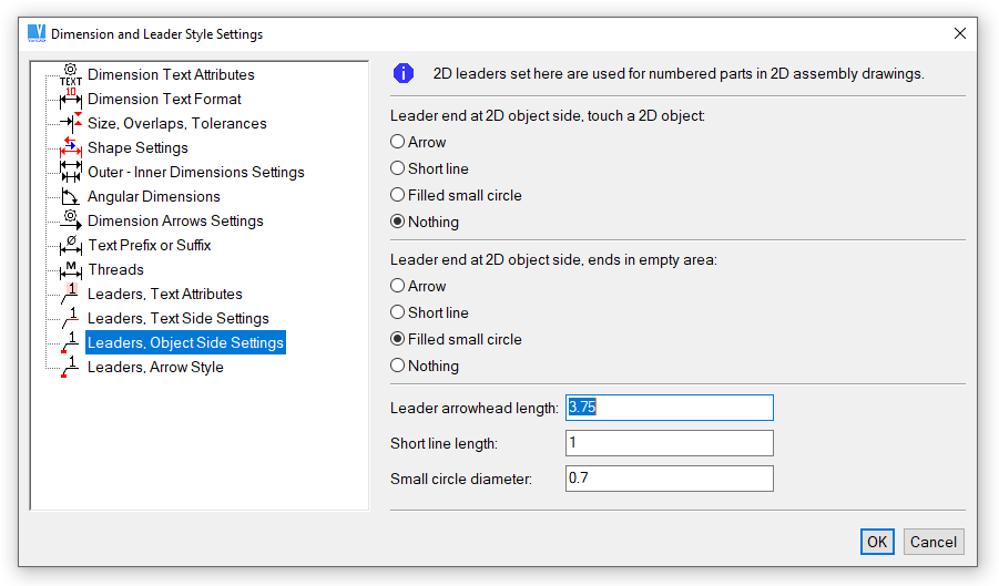
Leader style definition, object side of leader
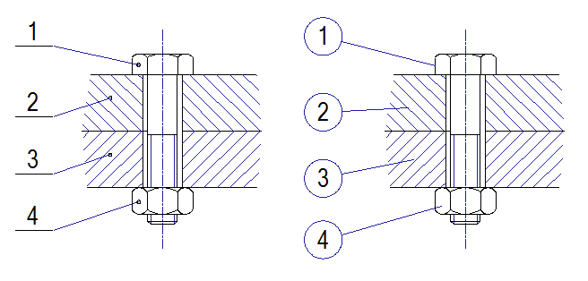
Example of leaders
To change existing leaders, right-click a leader and select action from pop-up menu.
| Edit leader. This allows you to change leader shape the same way, as it is created. |
| Edit leader text. |
If you defined item numbers in 3D and a 2D drawing containing leaders was created, you can change item numbers in 3D again. In 2D drawing, leaders are correctly rewritten or checked by following command:
Check and Update Leaders (Item Numbers) - CHLDR |
If there are leaders to be updated, following dialog appears:
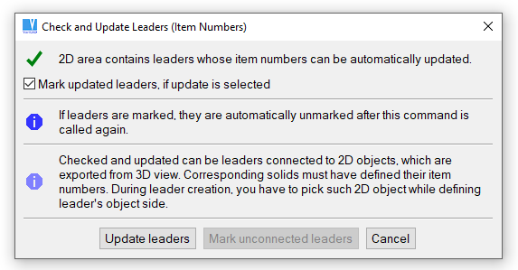
Update leaders
After confirmation, leaders are correctly rewritten and optionally highlighted. Highlighting of updated leaders is turned off by calling the update command again.
Edit Dimension Text - EDI |
Edits the text of a selected dimension. The same text editing options are available as when you created the dimension.
Move Dimension Text - MDT |
Uses drag and drop to move the text of a selected dimension. Be careful when using this function, because if you create more dimensions after moving the text, you could have overlapping objects.
Edit Dimension - EDM |
Change any attribute of a dimension. You can change everything about a dimension except for the original dimension definition points or the 2D dimensioned object. Dimension shape is defined the same way as if you create a new dimension. Similarly, you can change style, text or dimension shape.

|
|
|