2D Drawing
Displaying the 2D Drawing Area
To change the view, you can use the zoom functions or use the corresponding combinations of mouse buttons and keys.
Changing the View Using the Mouse and Keyboard
The following keyboard and mouse combinations can be used to manipulate the view:
- Zoom – using mouse wheel
- Zoom - Shift + left mouse button, or right then center mouse buttons. Moving the cursor up enlarges the objects; moving down shrinks them.
- Pan – press mouse wheel or middle mouse button, if it is separate. Then move the cursor.
- Pan - Ctrl + left mouse button or center then left mouse buttons. Moving the cursor shifts the view.
Display Functions
All functions controlling the display are available in the View menu or in corresponding icons.
Rebuilding Functions
Redraw - F6 |
Quickly refreshes the 2D area.
Regenerate - REG |
Regenerates and redraws all 2D objects.
Zoom Functions
You can change the size of the view by using the following zoom functions:
- Window - the view is defined by the two opposite corners of the desired view window.
- Zoom All - the view is sized so that all visible 2D objects will fit inside.
- Zoom Format - the view size is set according to current drawing format.
- Previous View - the display returns to the previous view.
By default, view change is animated. In command “CFG”, you can set animation properties or turn the animation off.
Saving Views
The Save View function enables you to save the current view for future use. To display a saved view, use the Restore View functions. You can save up to eight views. The Predefined Views toolbar makes it easy to switch between saved views. See also Saving Views.
2D Display Settings
2D Circle Display Settings
Settings of 2D objects displaying are available in command “CFG”, in 2D section. It enables you to increase the number of segments used for drawing of 2D circles. When the number of segments is higher, circles will always appear smooth even when zoomed closely. A high number of segments may slow down drawing speed, especially on slow computers and extremely large 2D drawings.
Cursor Settings and Coordinate Listing
Sets the aperture size of 2D cursor.
Displayed Cursor Coordinates - DCC |
Coordinates can be measured relative to a user-defined origin, or as DX, DY from the last point. Angle and radius from the last point are displayed automatically in most cases.
Types of 2D Objects
In 2D drawing you work with basic objects. These objects behave like individual entities when selected, and they can later be combined into blocks. The basic 2D objects are as follows:
- Line - includes single lines defined by two points or multiple (chain) lines
- Spline – 2D interpolated NURBS, used for curves, includes ellipsis
- Arc - includes arcs and circles
- Point - used mostly as construction aid
- Arrow - similar to lines, with arrowheads at endpoints
- Hatch - for filling closed areas
- Text - single-text lines or a note containing up to ten text lines
- Symbol - can contain lines, arcs, arrows and/or texts
- Dimension - can contain lines, arcs, texts or arrows
- Axes – created as axes of a circle, or by 2 points, or as axes of rotation surface exported from 3D
For more information about creating blocks, see 2D Blocks.
2D Drawing Attributes - Units, Formats, Scale
File attributes can be defined when creating a new file (see Creating and Opening VariCAD 2D/3D Files ). This section describes the functions used to change 2D drawing parameters such as drawing units, format and scale. Attribute functions can be found in the Tools menu.
Units
Change Units - CHU |
Change units in the current file by toggling between inches and millimeters. For example, an object defined to be 1” long will convert to 25.4 mm. Dimension text values do not change, nor do attributes of inserted mechanical parts. For example, Screw M10 will always have the same attributes, even if units are changed.
Format and Sheet Border
Drawing Format - FMT |
Changes the current drawing format. The format controls the view area, sheet border, and print attributes.
Sheet Borders Definitions - SBD |
You can define custom sheet border formats, modify existing formats, and define the method of drawing sheet borders.
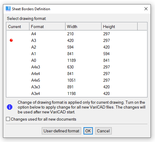
Formats window
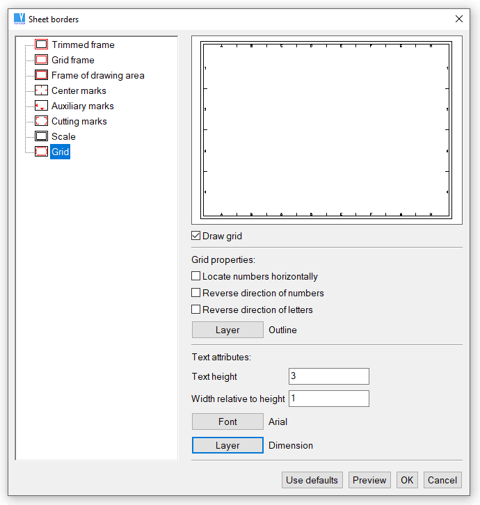
Sheet Border window
Sheet Border - BOR |
Creates a sheet border around the 2D drawing area. The lower left corner of border corresponds to the origin in global coordinates. Border width and length are determined by the drawing format. Border drawing method setting is defined in Units and Sheet Border.
Sheet Border in 2D Background
System draws a rectangle around the current sheet border, regarding the current drawing scale. The rectangle is drawn in the same style as an auxiliary grid. This format border is not printed and cannot be detected, it is only displayed. Contrary to the format border in the drawing background, you can insert a border created in a configured style from detectable and printable 2D lines. Such a border is a part of the current 2D drawing.
You can turn on/off drawing of the background sheet border in the command “CFG” (system settings). If turned on, the background sheet border is always drawn - it is not a part of a 2D drawing.
2D Drawing Scale
Drawing scale only affects 2D annotation objects such as text, dimensions, symbols and arrows. The scale affects the proportions of these objects. For example, with a 1:2 scale, a 100-mm line will print as 50 mm long. Text 3 mm high will print as 3 mm high. Changing the scale does not affect dimensions.
Change Drawing Scale - SCH |
Changes the 2D drawing scale. The scale is defined when the file is created, and this function can be used to change the scale. All objects in the file remain unchanged. New annotation objects such as dimensions and text are created in different proportions. We recommend finalizing the drawing scale before starting to assign dimensions.
Attributes of 2D Objects
2D objects have the following attributes:
- Layer
- Color
- Line Type
- Visibility (blanked or unblanked)
Working with 2D Layers
You can define up to 250 layers in each file. Each file contains one predefined layer named “0.” In 2D assembly, layers can be used to distinguish between separate details. For detail views or 3D view exports, layers should be used for distinguishing outlines, axes, dimensions, hatches etc.
Each layer is defined by name, color and line type. New objects are always created in the active layer. The active layer can be changed at any time, even during object creation. You can also change the current color or line type without changing the layer. For each object, its layer, color or line type can be changed at any time.
If objects from another file are inserted into the current file, objects from unknown layers are inserted into Layer 0.
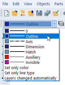
Setting the active layer
Layers - LAY |
Creates new layers, and edits or deletes existing layers. You cannot delete the active layer, a layer containing objects, or Layer 0. The command allows you to manage automatic layer switching.
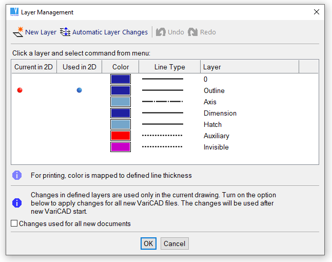
Layers window
Automatic Switching of Layers
Automatic layer switching can be set from the command CFG or LAY (see above). Automatic layer switching is useful for drawing 2D details. Layers are switched according to the executed function. Drawing functions like Line or Arc tools create objects automatically placed in Layer “outline.” Hatches are placed in “hatches;” dimensions are placed in “dimension.”
By default, automatic layer changing works with following layer order:
- The second layer is named “outline,” and is active during drawing functions
- The third layer is named “axis,” and is active while creating axes
- The fourth layer is named “dimension,” and is active while creating dimensions
- The fifth layer is named “hatches,” and is active while creating hatches
You can redefine the automatic layer switching. It is possible to select a single 2D drawing command or a group of 2D drawing commands and to assign a new layer automatically activated whenever the command is used.
Change Layer - MLA |
Changes the layer of selected objects to that of another object, or to a layer selected from the list of layers.
Highlight Layer - CHL |
Shows all objects on a specified layer, enabling you to check that the layer contains the correct objects.
2D Object Colors
For 2D objects, there are nine colors you can use. For 3D objects, there are 32 colors. Following dialog window contains list of colors available for 2D objects. The displayed color set is used for light background.
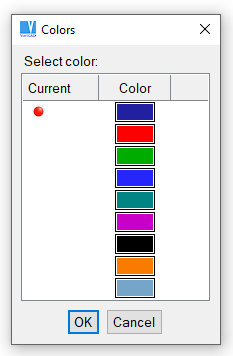
Line colors used in 2D drawing, for light background
For printing, line thickness is set according to color number. For color printers, you can map colors to other colors.
Change Color - MPE |
Changes the color of selected objects.
Line Types
For 2D objects there are 7 line-types available. Following dialog window contains list of line styles available for line style selection.
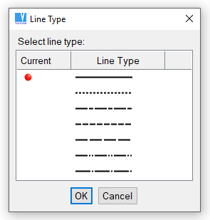
Line styles used in 2D drawing
Change Line Type - MLT |
Changes the line type of selected objects.
Visibility of 2D Objects
Blank 2D Objects - BLA, Ctrl + B |
Makes selected objects invisible. You can blank temporarily redundant objects, or objects that cannot be selected. Blanked objects are not printed, nor are they selected in selection windows.
Unblank 2D Objects - UBL, Ctrl + U |
Unblanks objects that were blanked, either in the entire drawing or in a specified area. You can also unblank individual objects, or all objects on a specified layer.
Work Sets
Work sets can be used to hold 2D objects. Work sets are useful when you want to delete or translate an entire set of objects. When inserting 2D objects from another file, you can place all new inserted objects into their own work set.
The following functions are used to manage work sets:
Add to Work Set - ATW |
Delete from Work Set - RFW |
Clear Work Set - CLW |
Deletes all objects from a work set
Highlight Work Set - CHW |
Helps you verify objects in the work set
2D Coordinate System
VariCAD uses two types of coordinate systems. The absolute coordinate system has its origin at the lower left corner of the drawing area. The user-defined coordinate system is, by default, identical to the absolute system until a new origin is defined. The user-defined coordinate system is unique for each file. When 2D coordinates are used, they are always relative to user-defined origin.
User Origin - UCO |
Locates the user-defined origin or resets to the absolute origin.
More convenient method to change or reset the user-defined origin is to use Increment Cursor Mode and select the change from dialog panel.