Libraries of Mechanical Parts
All mechanical parts can be found on the Parts menu. The following parts are available:
- Screws (bolts)
- Nuts
- Washers
- Pins and splines
- Rings
- SKF bearings
- ZKL bearings
- Rolled profiles (structural steel, beams)
- Flanges
- Spline shafts (only for 2D)
- Threads (only for 2D)
The parts are created according to the following standards:
- ANSI
- DIN
- JIS
- CSN EN ISO
All parts except flanges and beams have defined their names and attributes. The names indicate the part definition and basic dimensions according to the chosen standard. These data are used in BOM creation. Flanges and beams are intended for further modification, in contrast to screws, nuts, bearings and others.
Selecting Mechanical Parts
Select the standard and the type of part (screw, washer, etc.) from the Parts menu. The icon menu appears from which you can select a specific part, such as a hex bolt. To define the dimensions, you can select:
- One basic dimension from the list. The other dimensions will depend on this basic dimension. For example, for defining a bearing, select the shaft diameter.
- One basic dimension from the list, then other dimensions from the list. For example, for defining a screw, select the bolt diameter. Then a list of lengths appears, depending on the selected diameter.
- One basic dimension from list, then enter the other dimensions manually. For example, for defining a rolled profile, select the profile dimensions and then enter the desired length of the beam.
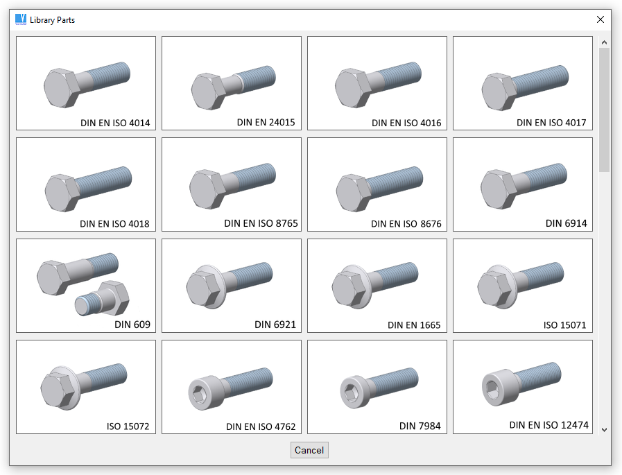
Example of selection of DIN screws
Configuring Mechanical Parts Selection Dialog
In “CFG” command, you can select “Library Objects Selection Settings”, and then configure:
- Image size at panel selection (selects type of screw, type of bearing…)
- Image size at panel defining dimensions (selects size like M10, M12…)
- Whether images at panel defining dimensions are transparent
There are two image size available. For 4k, only the large size is used.
Inserting Mechanical Parts into 2D
When defining part dimensions in 2D, you can also select the method of drawing or which view of the part will be inserted. For example, when a rolled profile is defined, you can choose whether or not to hatch the section. When defining a screw, you can choose to insert the front view, left view (axial view), and head.
Mechanical parts are inserted as blocks, and have predefined connection points. For details on inserting blocks, see Insert Block.
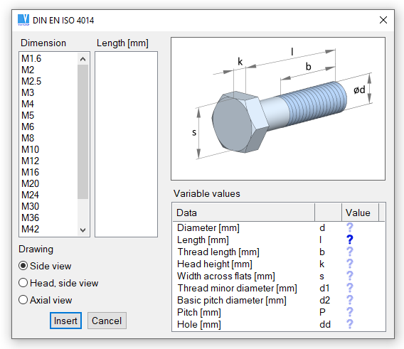
Mechanical part selection - 2D screw (bolt), dimensions are not yet selected.
Inserting Mechanical Parts into 3D
When defining part dimensions in 3D, you can:
- Predefine dimensions (see below).
- Select whether the part is inserted as a new part, or replaces a defined part. An example of replacement would be replacing one type of screw with another. If you define the parts to be replaced by name, you can replace all instances of a part in the entire file. See also Selecting Solids.
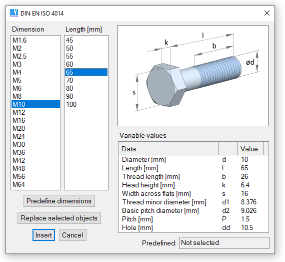
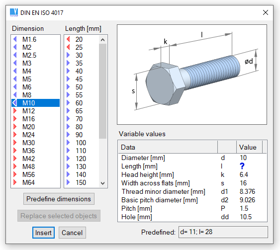
Mechanical part selection - 3D screw (bolt), dimensions are already defined
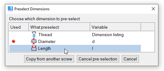
Pre-selecting Dimensions
Almost all types of mechanical parts allow you to pre-select one or multiple dimensions. These dimensions can be either measured in 3D space, or copied from existing similar part. For instance – inserting a screw, you can select another screw and its dimensions are then pre-selected in current dialog window.
Pre-selected dimensions are marked by corresponding icons in list of dimensions. Icons distinguish situation when a dimension is smaller than, equal or greater than pre-selected value, or if it complies or not. See images in following examples.
Individually measured values are:
- Thread specification
- A diameter (usually nominal diameter)
- Outer diameter – if it must be distinguished from a nominal diameter
- Inner diameter, similarly as an outer diameter
- Length
- Width
- Height
- Thickness
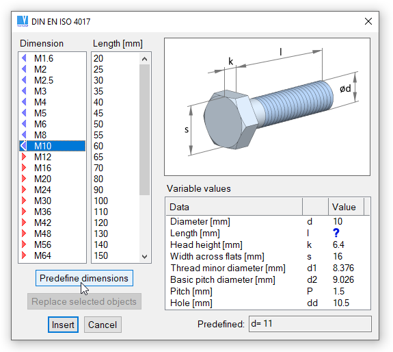
Select “Predefine dimensions” for length measurement. Thread specification is already predefined.
Select measurement of screw length.
Predefined lengths are marked in list by corresponding icons.
Options Available for Mechanical Parts in 3D
After right-click a mechanical part from library or selection of multiple parts, pop-up menu contains options related to library parts. These may be insertion of counter-parts, dimension change or type (standard) change.
Inserting Counter-parts, Inserting Nuts onto Screws
According to situation, menu offers:
- Insertion of a nut, if you click a screw
- Insertion of a nut, if you click an outer threaded surface
- Insertion of a corresponding washer in both such situations
- Insertion of a screw, if you right-click a surface of a cylindrical hole
- Insertion of a screw, if you right-click a surface of a threaded hole
- Insertion of bearing or ring, if you right-click an outer cylindrical surface
- Insertion of bearing or ring, if you right-click a surface of a cylindrical hole
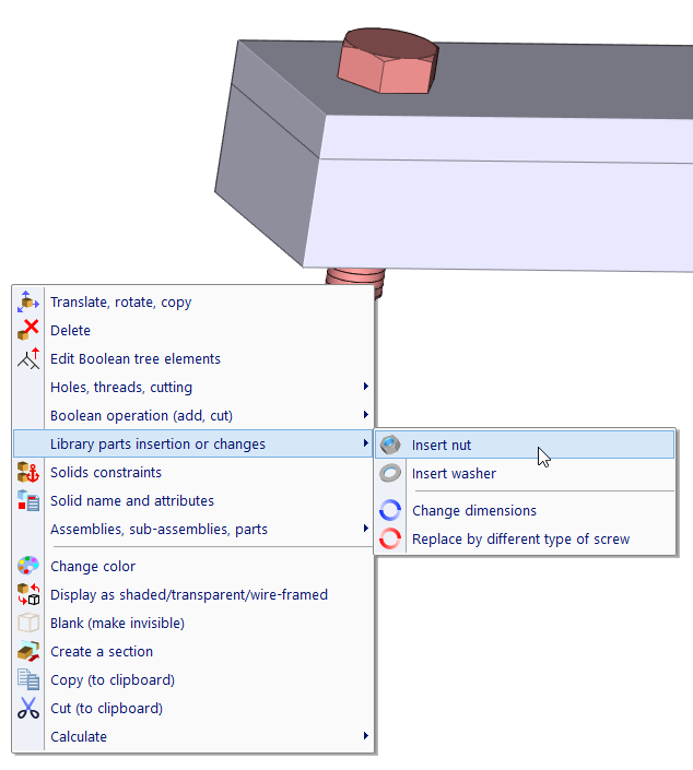
Right-click a screw, pop-up menu related to mechanical parts is selected
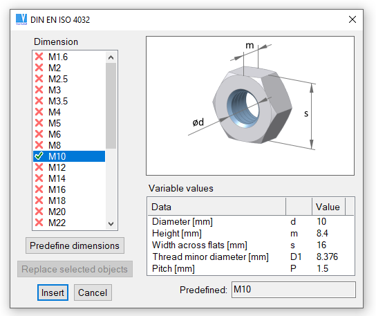
A panel with pre-selected thread of corresponding nut. The thread specification is defined according to detected screw.
Changing Dimensions or Type (Different Standard)
Right-click menu offers also change of dimensions of detected part. For instance, you can change length of an existing screw, diameter or thread etc. Dimensions in dialog window are pre-selected according to dimensions of detected part.
Apart of dimension changes, you can also change type (corresponding standard) of selected object. Again, dimensions in dialog window are pre-selected.
Changing Multiple Library Parts
Options allowing dimension or type change of library parts are available also, if you select multiple objects or if you select objects from assembly structure scheme. These options are active, if all selected objects are mechanical part libraries and if all of them have the same dimensions and are of the same type (the same standard).
Selecting Library Parts – Selection Filters
New features related to mechanical part libraries are completely available for parts inserted in version 2020-1.0 or higher. Obviously, they require additional data which are not present in older files. Some features are available for old library parts, similarly as for any other 3D objects. Right-click a threaded surface offers the same options for old parts, as for new ones.
To make sure you select library parts supporting advanced features, you can switch selection mode in 3D space. Right-click an empty area and choose “Selection method” in pop-up menu. Then, select “Detect library parts, advanced features”. For given step, only part libraries containing related data are detected. To end such selection mode, press ESC.
Modifying Mechanical Parts in 3D
Mechanical parts are created according to respective standards and they should not be modified. If you attempt to edit shape of library mechanical part, warning message is displayed. Rolled profiles (beams) or flanges can be edited without any warning.
Modifying Counter-parts, Drilling Holes for Screws
If possible, some mechanical parts have defined method of cutting or trimming other solids. For example, if you want to create a hole for screw, you can use screw as a “cutting tool” and create hole as exact negative copy of cylindrical part of screw. If you select corresponding modification of counterpart, a hole with diameter greater than screw diameter is created. Hole’s diameter is created according to standard, related to a diameter of the screw. For more information related to Boolean operations, see Boolean Operations.
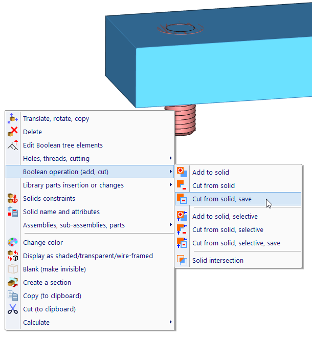
A screw inserted into full material is selected as a tool for Boolean cut.
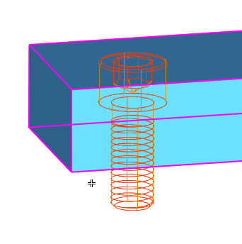
Selection of a solid the tool (screw) will be cut from (this drills a hole).
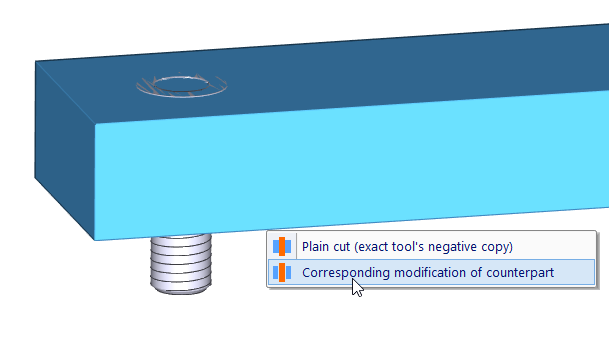
Menu with option Plain cut vs. Modification
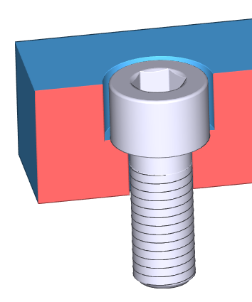
A solid in section, after modification.
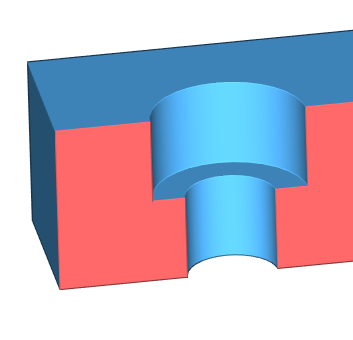
A solid in section after modification, without the screw