Selecting 2D Objects
While working with 2D objects, you almost always need to select other objects. In a typical function, you must select one or multiple objects, finish the selection, and then the function processes the selected set. For example, selection is used when deleting objects, translating objects, changing object color, etc. Temporary toolbars provide selection options.
Methods of Selecting
The most direct way to include objects in the selection set is to left-click on them. Objects are selected if they are within the cursor aperture, and selected objects are highlighted in a different color.
A temporary toolbar appears during object selection, which provides additional selection options. All options are also available on the Select menu. You can select single objects, or groups of objects that share attributes such as a particular color. You can select groups of objects from the entire drawing, or you can use selection windows. You can also access selection options by entering the relevant command keys (which are not case-sensitive). When using commands, the desired object must already lie within the cursor aperture.
Selecting Types of Objects
These options enable you to select single objects of a certain type that are found within the cursor aperture. When using these selection options, automatic detection is irrelevant.
| Icon | Key | Use |
| L | Selects a line | |
| Q | Selects a spline | |
| A | Selects an arc or circle | |
| P | Selects a point | |
| S | Selects a symbol | |
| Shift + 6 (^) | Selects an arrow | |
| C | Selects a hatch | |
| N | Selects a text | |
| D | Selects a dimension |
Selecting Groups of Objects
| Icon | Key | Use |
| N/A | Selects all objects | |
| R | Selects objects completely inside the selection window | |
| I | Selects objects completely or partially inside the selection window | |
| U | Selects objects completely or partially outside the selection window | |
| O | Selects objects completely outside the selection window | |
| V | Selects objects on a specified layer | |
| B | Selects objects of a specified color | |
| Y | Selects objects of a specified line type | |
| T | Selects a group of objects of a specified type | |
| 1…8 | Selects objects from work set 1 - 8 |
Using Selection Windows
Run command CFG, section 2D and sub-section “2D Object Selection Settings”. Here you can determine when and how selection windows will be used. If, during a selection, you click in the drawing and nothing is selected, you can set the system behavior to do one of the following:
- Display a warning message
- Start a selection window whose behavior must be determined
- Start a selection window whose behavior is defined by which corner the window starts (upper left, lower right, etc.)
Selecting Objects Related to 3D Solids
| Icon | Key | Use |
| E | Selects a profile to be used to create a solid. The profile is selected segment by segment. | |
| F | Selects a profile to be used to create a solid. The profile is identified automatically. | |
| M | Selects all objects linked to a single 3D solid. These objects are created by exporting a 3D view. | |
| G | Selects all objects belonging to a 3D view export. |
When you create a 2D documentation from 3D parts or assemblies, you may need to select entire view (Top view, Front view…) quite often. To do so, press and hold Ctrl and move cursor over 2D objects. All objects belonging to an exported view are detected. Left-click them to finish selection.
This way, you can select 2D lines, circles or arcs displaying corresponding 3D objects, and also dimensions, hatches or axes, if they are connected to 3D export.
If the view is once exported and you want to move it into a different location, it is necessary to select all objects from the view. Otherwise, connections to 3D may be lost.
Limited 2D Selections
Some functions, such as Fillet and Chamfer, require you to select a limited number of objects. In this case, there is no need to finish the selection group. If you need to select two segments that share a corner, you can select the segments individually or select the corner itself. To select by using the corner, click when the V symbol appears on the corner. See also Creating Corners, Chamfers and Fillets. Prior to calling command, you can press and hold Shift, move cursor over a corner and when detected, right-click to select fillet or chamfer.
Deselecting Objects
| To delete objects from a selection set, click Select/Deselect icon and use the normal methods to select objects - each selected object will return to its unselected state. Pressing X while selecting will also deselect objects. |
Finishing the Selection
Press Enter or right-click to complete the selection set, or click the corresponding icon in a toolbar.
Selecting 2D Locations
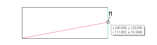
Most 2D objects require geometric input in the form of X, Y coordinates. VariCAD makes it easy to select certain significant locations relative to existing objects. To select a point on an object, move the cursor over the object so that it is highlighted. Clicking on the object will select the point closest to the cursor. If cursor approaches a snap point, such as an endpoint or midpoint, a symbol appears next to the cursor. Clicking when you see this symbol selects the point. The following letters indicate snap points:
| Letter | Snap Point |
| E | Endpoint |
| M | Midpoint |
| 5 | Center of circle or arc |
| X | Intersection |
| S | Connection point of a symbol or block |
| 1 | 0-deg point of a circle or arc |
| 2 | 90-deg point of a circle or arc |
| 3 | 180-deg point of a circle or arc |
| 4 | 270-deg point of a circle or arc |
You can also use icons, keys, and Snap menu items to specify snap points or other geometric locations. If you select a snap-mode by key pressing, the desired point or related object must already be within the cursor aperture. The Snap menu appears if you press simultaneously right and left mouse button while 2D location is defined.
Automatic detection of a snap point
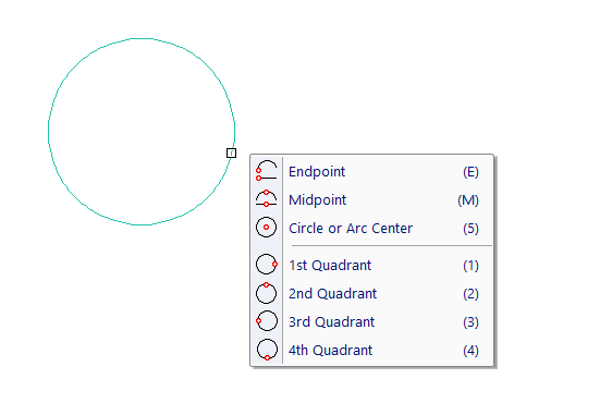
Pop-up menu with snap options – displayed after right-click of detected object.
If you need temporarily turn off automatic detection during a location input, press and hold F2 - see Turning off Detection Temporarily.
2D Snap Points
| Icon | Key | Location |
| E | Nearest endpoint | |
| M | Midpoint | |
| 5 | Center of an arc or circle | |
| O | Nearest point on an arc or line | |
| P | Point (must lie within cursor aperture) | |
| Z | Insertion point of a block or symbol | |
| S | Connection point or insertion point of a block or symbol | |
| N/A | Nearest dimensioned point | |
| N/A | Leader, text-side point | |
| 1 | 0-deg point of a circle or arc | |
| 2 | 90-deg point of a circle or arc | |
| 3 | 180-deg point of a circle or arc | |
| 4 | 270-deg point of a circle or arc | |
| F | Intersection of two segments (select both segments, can also find intersection of segment extensions) | |
| Spacebar | Nearest grid point | |
| C | Intersection of nearest construction lines |
Combination of Location Points
| Icon | Key | Location |
| G | Defined distance from the nearest line endpoint | |
| A | Intersection of a selected object and a line created from the last point at a specified angle | |
| 6 | Intersection of a selected object and a line created from the last point, perpendicular to this object | |
| T | Tangent point on a selected object, directed from the last point | |
| B | Halfway between two defined points |
Points Defined by Keyboard Input
| Icon | Key | Location |
| K | Enter X, Y coordinates | |
| D | Enter DX and DY from the last point | |
| R | Enter the distance and angle from the last point |
Other Points and Functions
| Icon | Key | Function |
| W | Redefine the user origin | |
| I | Exact current cursor location | |
| TAB | Fixed length, angle or coordinate |
Fixed Length, Angle or Coordinate
This method of 2D input allows you to use many convenient combinations. It is always available by pressing TAB. Then, a dialogue panel is open. If you continue pressing TAB, you change focus of input of X, Y, radius or angle value.
If you enter only one value, for instance X coordinate, next 2D input has fixed X coordinate. Or, if you enter only radius (length), next 2D input is always rounded to fixed distance from previous point. During drawing of line, you can create a fixed length segment.
If you enter two values, input is exactly defined. This allows you a combination of input of fixed coordinates, input of location in distance and under an angle etc.
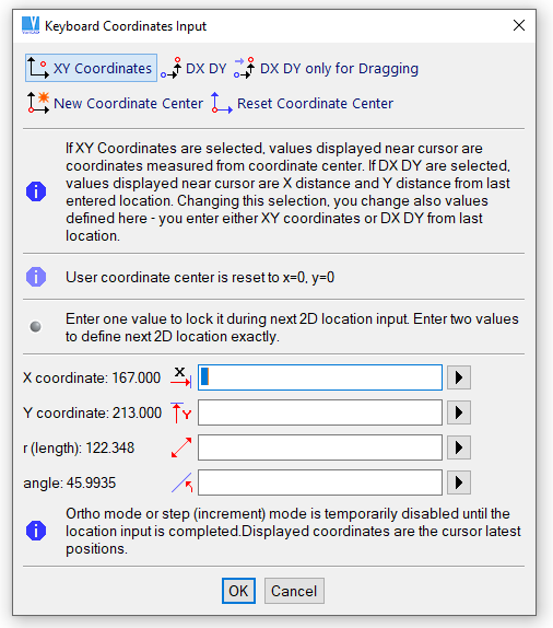
Keyboard coordinates input
Defining Angles and Directions
Some functions, such as symbol insertion or mechanical part insertion, allow you to determine the rotation angle of inserted objects relative to line segments. Angles are measured counterclockwise from the +X direction (to the right of the origin).
To define an angle according a line direction, click a line. Then, four arrow icons appear – two along line, opposite each other. Next two arrow icons are perpendicular to line, opposite each other. Move cursor around the center of icons. Arrow in direction close to cursor is highlighted. Left-click a desired location, the current direction of angle is used.
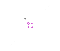
Angle input, measured from a line