2D Drawing Aids
The following aids are available to help you while creating 2D objects:
- Grid
- Construction lines
- Temporary construction (leading) lines
- Transient leading lines
- Ortho mode
- Increment cursor movements
Ortho mode or increment cursor movement is displayed at right end of status bar. Also, corresponding icons in tool-bar are checked.
Grid
The orthogonal grid provides better drawing orientation and enables snapping to grid points. The grid is displayed in two levels of brightness. When the grid density is too high to display, the grid is automatically turned off. Snap distances can be smaller than the grid spacing.
The grid can be especially useful when translating entire sections of a 2D drawing or inserting 3D view exports. Grid snapping is available even when the grid is not displayed. Entered values are rounded to the nearest multiple of the snap distance. If you want to use the same grid settings in new documents save the current settings as default.
Grid – GRI, Ctrl + G |
Sets the grid spacing or turns the grid on or off.
Construction Lines
Construction lines are “auxiliary” or temporary lines, independent of any other objects. You can create individual constructions lines or a mesh of them. Objects or other construction lines can be placed at the intersection points of other constructions lines – either intersection between two construction lines, or intersection between a construction line and a line, arc or NURBS curve.
Construction lines can be created as vertical, horizontal or angular. You can predefine two angles for angular lines. If you create a construction line or if you delete one or multiple lines, the step can be undone or redone again – similarly, as for any other 2D or 3D object.
Construction line functions are available from the Construction Lines toolbar, and from the Objects / Drawing Aids menu.
Creating Construction Lines
You can create construction lines as:
- Single lines passing through a selected point
- Groups of lines that have a specified distance from a specified origin (a negative distance creates new construction lines in the opposite direction)
- Groups of lines that are offset at a specified distance from the previous line (a negative distance creates construction lines in the opposite direction)
- Single lines tangent to a selected circle or arc
Deleting Construction Lines
You can delete all construction lines, delete a selected line, or delete all lines by type (all horizontal, all vertical or all angular).
Creating Multiple Construction Lines
Apart of creation of individual lines or group of lines, you can create multiple construction lines – as the most convenient method.
Create Multiple Construction Lines - CCL |
This function creates one or multiple construction lines of all types – horizontal, vertical or angular.
Following options are available:
| Create Horizontal/Vertical Construction Lines – select a location and then direction the new construction line (lines) will be created at. The line or lines are created according to current selections – at a distance from the selected location, at a distance from the previous line or they are dragged by cursor |
| Create Angular Construction Lines – under predefined first angle, similarly as horizontal/vertical lines |
| Create Angular Construction Lines – under predefined second angle, similarly as horizontal/vertical lines |
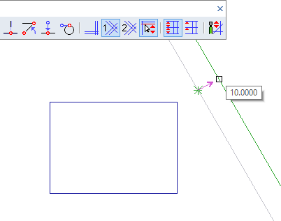
| Drag Construction Line by Cursor – if this option selected, a new construction line is dragged by cursor until you select a location. By default, increment mode of dragging is used – for instance, the new line is dragged in increments of 1 millimeter. Distance from location is displayed near the cursor. If this option is turned off, the distance of a new construction line is defined by keyboard input or measurement. |
| Set Dragging Increment or Angles – sets increment of dragging, or predefined first and second angle of angular construction lines. |
| Measure Distance from Selected Point |
| Measure Distance as Offset from Previous Line |
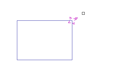
Selecting a direction of a new construction line
A construction line dragged by cursor, according to the previous selection

Construction Lines toolbar
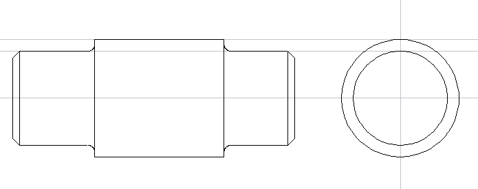
Example of construction lines used to create a side view
Temporary Construction Lines
Temporary construction lines (leading lines) are automatically created at the last defined location and in these situations:
- Drawing of 2D lines, poly-lines or multi-lines
- Creation of temporary boundaries for extensions, or temporary cutting lines
- During dragging of objects, at a location of dragging point definition
- During stretching, at a location of dragging (reference) point definition
By default, these temporary construction lines are active in 2D drawing in 3D (in sketching). You can stick cursor at these construction lines and easily follow horizontal or vertical direction. In 3D sketching, you may not recognize directions of X or Y axis well, because of view rotation.
Transient Construction Lines
Transient construction line or lines are temporarily displayed, if X or Y cursor coordinate approaches:
- Location x=0, y=0 (coordinates origin)
- Marked point, like end-point or mid-point
- Poly-line start point.
Transient lines disappear, if cursor moves away from them more than defined distance. On the other side, you can follow a transient line by cursor movement until you reach an intersection of the transient line and a 2D object.
To turn on or off temporary or transient construction lines for sketching or 2D mode, run command “CFG”, or select Ortho Modes, Leading Lines
Increment Cursor Mode
When not in Increment mode, the cursor moves smoothly and defined locations are based on display resolution. When using Increment mode, cursor locations are rounded to the nearest multiple of the increment distance. The square or arrow cursor movements are still smooth; only the resulting locations are rounded. Crosshair cursor movements “jump” in the defined steps. Increment mode is indicated in the Status Bar. Increment mode is especially useful when used in conjunction with a user-defined origin.
Increment Cursor Mode - STP, F9 |
Turns Increment mode on or off, or sets the XY increments of cursor movement. This command also allows you to set or reset 2D coordinate origin.
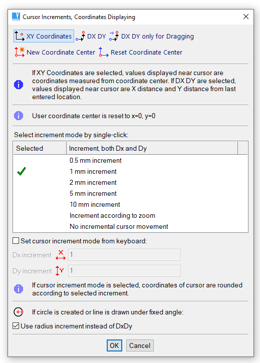
Setting cursor increments or coordinates origin
Ortho Mode
Ortho mode is an obsolete method. It is available as a legacy option. We recommend to work with temporary and transient construction lines rather than with Ortho mode. Besides, Ortho mode may be inconvenient in stretching, where you may have drawing plane displayed under various view angle.
In Ortho mode, created lines are always horizontal or vertical, according to current position of cursor. You can use Alternating Ortho mode, in which lines alternate between horizontal and vertical, regardless of cursor position. Ortho mode is indicated in the Status bar. Also, a corresponding icon in tool-bar is checked.
Ortho Modes, Leading Lines |
This command sets Ortho mode, turns off Ortho mode or configures temporary construction lines (leading lines).
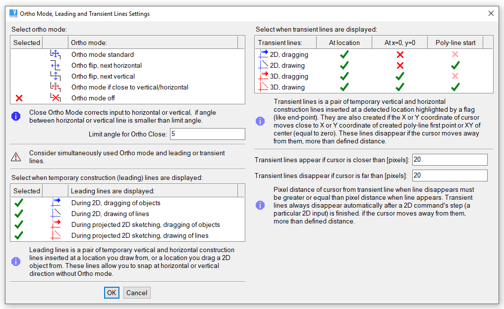
Ortho modes and leading lines settings.
Following commands manage various Ortho modes individually:
Ortho On - F11 |
Turns on Ortho mode.
Ortho Alternating H/V |
Turns on Ortho mode, alternating horizontal and vertical lines. The first line is horizontal.
Ortho Alternating V/H |
Turns on Ortho mode, alternating horizontal and vertical lines. The first line is vertical.
Ortho if Close to Vertical/Horizontal |
Ortho mode is used, if the angle of the current cursor location measured from the last input is close to horizontal or vertical direction. The angular limit can be set.
Set Close Angle for Ortho |
Sets the angular limit for the mode described above.
Ortho Modes – Shift + F11 |
Opens pop-up menu with all Ortho mode possibilities.
Ortho Off |
Turns off Ortho mode.