3D Comprehensive Shapes
Creating and Editing 3D Texts
3D texts extruded into space can be defined and edited the same way as 2D texts. You can write text, select text height or text font. For 3D, extrusion height and draft angle is defined. Text font is exploded into 2D contours and these contours are then extruded. Optionally, you can explode fonts into lines and NURBS curves, or only into set of short lines. Also, you can create set of single extruded solids instead of a complex text object. 3D text objects can be added to or cut from any selected solids.
Create 3D Text – TXT3D |
This command creates 3D texts.
To edit an existing 3D text object, right-click any letter and select 3D text editing from pop-up menu. Edit of the entire text object rebuilds all text letters in one step. It is always possible to edit contours of letters individually (as for any extruded solids), and to change their locations individually. Moreover, a 3D text can be created as plain extrusion with no further connections to original text value.
| Edit 3D Text - this option is available, if you click a letter created as a part of 3D text object. Then, you can edit the entire text at one step. |
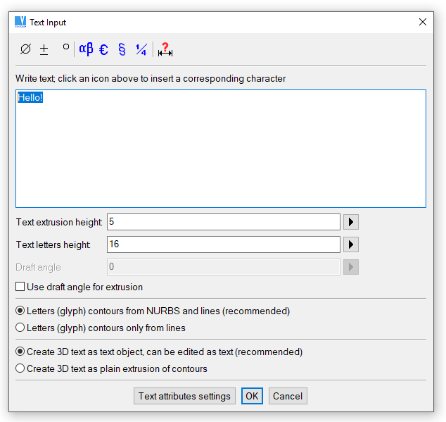
3D text definition

An example of 3D text
Pipes and Wires
Pipes or wires are created as a set of cylindrical segments and elbows. Define diameters and the elbow radius first. Then define a path of the pipe or wire in space. To define the path, you can use similar tools as for solids insertions or translations. Location of the tri-axes tool defines a location of the pipe segment endpoint. Before each confirmation of the location, you can easily redefine tri-axes tool position or adjust this position according to other spatial objects. See Transforming and Copying Solids for basic location modes.
You can define straight segments, while each connection is automatically rounded by an elbow. You can insert an elbow directly at the finished straight segment and define its rotation. You can also bend a pipe around a corner in space as well as around or according to another pipe’s elbow. You can finish the pipe selecting an axis (for instance flange’s axis or hole’s axis) - an elbow and straight segment is created. The straight segment is finished right at the selected axis. The next location selected anywhere at the selected axis allows you to create a pipe straight into the desired location under the desired direction.
For definition of pipes or wires in space, you have more additional options available than for locations of solids:
| Icon | Use |
| Elbow radius redefinition | |
| Diameter redefinition | |
| Creates elbows between straight segments automatically, segments are defined by endpoints | |
| Creates single elbow defined by start tangent and point | |
| Creates elbow and straight segment to intersect selected axis | |
| Locate at intersection of two selected axes | |
| Pipe/wire segment endpoint at current location |
Clicking the inner part of the tri-axes tool, you can obtain more options for corresponding axis than for locations of solids:
| Icon | Use |
| Dynamic rotation around selected axis, reference point at end of X axis | |
| Dynamic rotation around selected axis, reference point at end of Y axis | |
| Dynamic rotation around selected axis, reference point at end of Z axis | |
| Bend pipe around a corner, start at direction of selected axis | |
| Bend pipe around another elbow or axes intersection, start at direction of selected axis |
While defining a path of a pipe or wire, Enter or right-click has different meanings according to the given situation. If a segment is inserted and no new location of tri-axes is defined, press Enter (or right-click) causes the pipe creation is finished. All previously defined segments are merged into a single pipe or wire. If a segment was created and a new tri-axes location is already defined, press Enter (or right-click) defines new segment’s endpoint. VariCAD uses different cursors to distinguish each situation:
| Cursor | Use of Enter | Use of Step Back |
 | End point of segment is defined | If a segment was created before, tri-axes are located back at the endpoint of this segment. Otherwise back to geometry confirmation |
 | Pipe or wire is finished | Last segment is removed |
Pipes - PIPES |
Creates pipes in space. Radial intersection is ring – defined by outer and inner diameter.
Wires - WIRES |
Creates wires in space. Radial intersection is circle – defined by diameter.
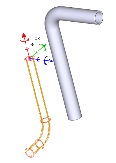
Creation of pipe
Sweeping of 2D Profiles
Sweeping of 2D profiles is similar as creation of pipes or wires, except that you sweep a closed contour created as a 2D profile. At first step, create a 2D profile in sketching plane – similarly as a profile for extrusion, for example – see Sketching of a 2D Solid Profile. Then, define a 3D path the same way as for pipes or wires.
Sweep 2D Profile along 3D Path - SWP |
Offset Patches – Thick Shells
Shell is created as the offset patches are connected to the selected patches at a given thickness. Select patches on a solid first. Then define a thickness. You can select whether the resulting shell is created as outer layer to the selected patches (creation in a direction of the normal), or the selected patches are outer layer of resulting shell (creation against a direction of the normal). You can select also if the original solid remains in space or is removed after the shell creation. In both cases, copy of the shell pattern is stored in the shell object and remains available for further shell shape editing.
Selecting patches for shell definition, you can select patch by patch or use the following option:
| All solid’s patches are selected. Then you can some of them deselect. |
Shell objects can be used as sheet metal parts.
Offset Patches (Shells) - OFP |
This function creates shell objects.
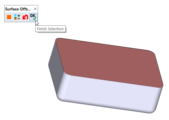
Creation of shell
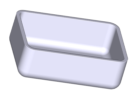
Shell defined in previous example
Threads in 3D
Threads can be created on an existing outer cylindrical surface, as a threaded hole or by inserting a threaded cylinder (a threaded end of shaft, for instance). Once created, the threads are properly exported into 2D drawing area or into STEP files. Checking interferences, the threads are correctly distinguished not only according to their diameters, but also according to their pitches and types. If a solid which contains threads is to be rescaled, scaling values are limited to available standard thread diameters.
Parts inserted from mechanical parts libraries are correctly fitted with threads, too. The threads are present at screws or nuts inserted from the libraries. Screws and nuts created in versions prior to VariCAD 2008 are not automatically changed to objects fitted with threads.
If a threaded surface is exported into 2D drawing area and if you perform dimensioning, dimensions of threads contain corresponding texts automatically – see Thread dimensions.
If you create a threaded hole or outer threaded cylinder (a screw), you can select a thread from a list of threads:
- Metric Threads, for work with ISO units (millimeters)
- Unified Screw Threads, for work with imperial units (inches)
- Pipe Threads, ISO 228
Functions available for thread creation:
Threaded Hole - THH |
Threaded Cylinder (Screw) - THS |
Outer Thread Cutting Tool - OTC |
Outer thread can be cut only at a diameter equal to a standard thread diameter.
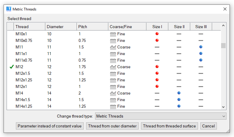
Selecting a thread from a list of threads