Surface Development (Unbending)
Surface Development enables you to create an unbent (flattened) version of a 3D surface and transfer it to a 2D drawing. This enables you to represent parts created from sheet metal. Moreover, you can create these parts as filled objects, if you only need to obtain a developed surface. Each bent surface can be created as an outer or inner shell.
You can develop only surfaces through which lines can be laid, such as cylindrical or conical surfaces. Planes can also be developed, but they are displayed with no change in 2D. You can select more than one surface to develop. For multiple surfaces, the function resolves connections of developed patches.
These unbent objects are created in the 2D drawing at a 1:1 scale, and can therefore be used as template, if 2D drawings are plotted. Surface outlines are lines or curves approximated into short line segments. The XY coordinates of outline points can be saved to a text file. Leaders can also be placed at outline points.
If the sheet is thin enough, you can ignore its thickness. Otherwise, the thickness must be defined and its value is incorporated while calculating the surface development.
Surface Development - SDE |
The following properties must be defined before selecting the surfaces to develop:
- Whether the text file with outline points will be created
- Whether the origin and leaders will be created in 2D development
- Material thickness (if undefined, zero is used)
- Line attributes used in the 2D drawing
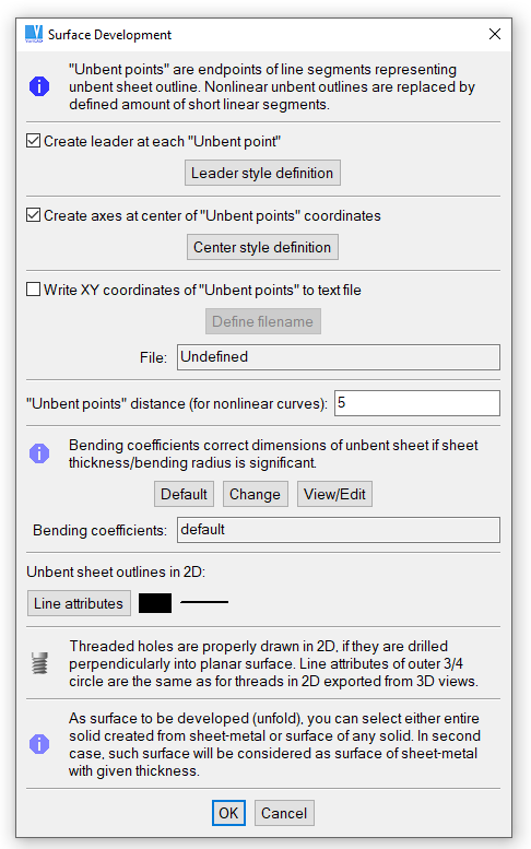
Surface development window
After defining these properties, select the surfaces to be developed. Press “Enter” or right-click to finish surface selection. The following are additional options:
| Select the entire solid created from a sheet metal. This option is available only if no other patches are selected. If the entire solid is selected, you can deselect some of its patches, if necessary. |
Other available options allow you to switch between select and deselect mode, undo previous selection or finish selection and perform unbending.
After selecting surfaces, define the material thickness. If the selected surfaces are surfaces of a sheet metal, the thickness is calculated automatically and you can confirm its value. Otherwise, define whether the thickness is significant. If yes, then define thickness value and select if the surface is an outer surface of the sheet metal or if the sheet metal is an additional layer of the surface.
The final step is to drag to insert the unbent surface in the 2D drawing. If necessary, define the surface origin and leader positions.
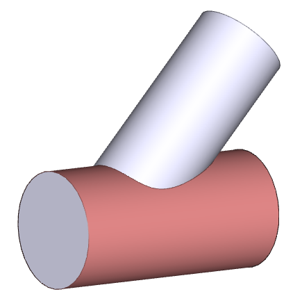
Selection of surface to be developed (unbent)
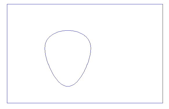
2D display of developed surface
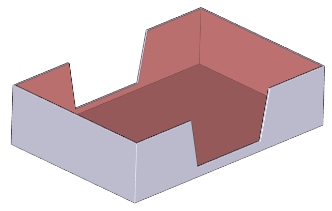
Selection of multiple surfaces
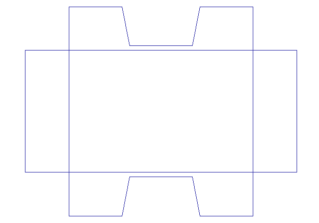
2D display of developed surfaces