Getting Started
VariCAD User Interface
The VariCAD window is divided into three parts. The largest part is the 2D drawing / 3D modeling area. The part above the modeling area contains the Menu Bar. Below the modeling area is the Status Bar. Toolbars are docked in various places on the screen, and toolbars can be undocked to become floating windows.
Working with Multiple Monitors
If VariCAD detects two monitors first time, a dialog panel is displayed and you may select from following options:
- Use only one (primary) monitor. In such case, VariCAD window and all dialog panels are open at primary monitor.
- Use two monitors, drawing at right (secondary) monitor.
- Use two monitors, drawing at left (primary) monitor.
If two monitors are used, some dialog panels (like BOM, list of assembly structure, panel containing icons for solid transformations …) are displayed at monitor opposite to main VariCAD window. Run command “CFG” to modify which panels are displayed at second monitor.
Two monitors can be configured if both desktops have the same dimensions and in virtual desktop, they touch each other from left to right and have the same Y coordinate origin.
If your computer (if it is a notebook) contains an external monitor and external graphic card, VariCAD selects the external graphics by default.
2D/3D Area
This area contains the 2D or 3D objects you create. You can switch between 2D and 3D at any time, and menus and toolbars will change accordingly.
Status Bar
For functions that do not require a window for input, all messages and prompts are displayed in the Status Bar. The following items are displayed on the right side of the Status Bar:
- In 2D and 3D, current units in millimeters or inches
- In 3D, dragging distance or dynamic rotation.
- In 2D, Ortho mode and Increment mode
- In 2D, cursor coordinates. Coordinates can be measured relative to a user-defined origin, as DX, DY from the last point, or as an angle and radius from the last point.
Cursor coordinates in 2D or dragging distance in 3D is also displayed near the cursor by default. If Ortho mode or cursor Increment mode is active, corresponding icons in tool-bar are checked permanently.
Toolbar Icons
Toolbars can be docked to sit above, below, or to the side of the drawing area, or they can be used as floating windows. Toolbars typically contain groups of icons for related functions, such as drawing functions, basic solids, dimensioning, etc. We recommend not removing the following toolbars:
- Switch to 2D/3D
- 2D layer selection box
- Command box
You can right-click on any toolbar to invoke a menu enabling you to add, delete, or reconfigure toolbars. You can also manage toolbars by using the following function:
Toolbar Settings - TLBS |
Configuration of toolbars for small icons is different than configuration of toolbars for large icons.
Dialog Windows - Cancel and Back Buttons
Optionally, VariCAD windows may contain buttons for “Cancel” and “Back.” Then the “Cancel” button cancels the current function completely. By default, only “Cancel” button without “Back” button is used. Then the “Cancel” button performs a step back.
Right-click while the cursor is inside the window is equivalent to click a highlighted button, usually the OK button.
Mouse Buttons
For both 2D and 3D, the default mouse settings are as follows:
- Left button - used for selecting objects or defining position. If the left button is pressed and held and if you move the cursor, selection window starts
- Middle button - proceeds one step back within a function. If the middle button is pressed and held and if you move the cursor, pan starts (display content is moved). Pressing a mouse wheel has the same effect as pressing the middle button – separate middle button is not a usual mouse configuration.
- Right button - completes a selection, equivalent to pressing Enter or OK. If the right button is pressed and held and if you move the cursor, 3D display rotation starts. Right-click object opens a pop-up menu with related features. Right-click an empty area opens a menu containing features related to current 2D/3D state.
- Mouse wheel – rotation enlarges or shrinks the display content (zoom). You can configure the rotation direction – whether the rotation toward you enlarge or shrinks the zoom.
- For 5-button mouse, VariCAD supports these additional buttons. They perform Undo or Redo actions.
Within a selection or location input, you can simultaneously press right and left mouse button, or press Ctrl + Right button to obtain a pop-up menu with currently available options.
See Tips and Tricks for more information.
3D Mouse
For 3D view rotation, and 3D or 2D zoom or pan, VariCAD can optionally work with 3D mouse using drivers issued by 3DConnexion. According to 3D mouse model, you can work with additional buttons, too.
You can configure 3D mouse sensitivity and direction of movement or rotation, separately from driver settings. Run “CFG” command and in general section, select “Space Mouse Settings”.
If you are using a 3D mouse and if you right-click standard mouse button during display change, a pop-up menu with following options appears:
- 3D mouse view rotation on/off (on/off according to current state). If the rotation is turned off, only pan or zoom can be controlled
- 3D mouse pan/zoom on/off (on/off according to current state). If the pan/zoom is turned off, only view rotation can be controlled.
- View rotation center to defined point. This option is very useful especially for large models and greater zooms – you can redefine view rotation behavior whenever it is necessary.
In 2D mode, only pan and zoom can be controlled. If pan and zoom is turned off in VariCAD, it still works in 2D.
Invoking and Running VariCAD Functions
To invoke a function, you can:
- Right-click an object (see below).
- Select objects, then finish selection with right-click (see below).
- Click a toolbar icon. Tool-tip appears when you hold the cursor over an icon – it helps you remember the icon meaning.
- Use the Pull-down Menu. Some functions are embedded in several menu layers.
- Enter the command in the command box. A command history list is created; in which you can access previously used functions.
- Use hotkeys. Ctrl, Shift, Alt, and F-keys are used, sometimes with other keys, to invoke functions. When Ctrl is used, the current command ends and is replaced by the new one. The F-keys only interrupt the current function temporarily. You can configure usage of hot-keys.
Some functions always behave as the embedded ones – current function is interrupted temporarily regardless the method of embedded command calling. For instance, you can change a view or measure distances without the necessity of finishing the current command. Measuring distances is especially convenient. You can “Cut and Paste” results – use them as input for any values.
For a list of all embedded functions, see Embedded Functions
You can configure the usage of hot-keys. It is possible to re-assign commands to selected hot-keys. Run command “CFG” to maintain the settings.
Finishing VariCAD Functions
Many VariCAD functions are “continuous.” For example, when drawing a line, you define two endpoints. After the line is finished, you can begin creating a new line. To end and exit a function, you can:
- Call a new function
- Press ESC if there is not a dialog window
- Press ESC if there is a dialog window - if necessary, multiple times to perform all steps back
If you exit a function, the Status Bar displays “Ready.” If the cursor is still within the drawing area, you can right-click an empty space to invoke the previous function from pop-up menu containing a list of commands history.
Stepping Back within a Function
Functions are typically performed in steps. For instance, when drawing a line, Step 1 is to define the first point, and Step 2 is to define the second point. To go one step back, you can:
- Press Ctrl + Z
- Click the middle mouse button (mostly, the same is to press mouse wheel), or press Ctrl + Backspace
- Press ESC or “Cancel” in dialog window (ESC outside a window cancels the current function completely)
- For 5-button mouse, press a corresponding mouse button.
Stepping back enables you to repeat or correct previous input without having to exit the function. Using Undo and Redo does not have the same effect; these functions actually change the 2D/3D object database. See Undo and Redo
Selecting Objects between Functions
You can also select objects between functions (commands) and after the right-click, select a function from the pop-up menu. You can also right-click an object and then select a function from the pop-up menu. The offer of functions is, however, limited. Mostly editing functions are available.
You can use these additional methods to select objects between commands:
- To select all objects, press Ctrl + A.
- To select a part of solid in 3D (like a hole, fillet...), press Ctrl while moving the cursor.
- To select 3D edges for blending or 2D corners for fillet/chamfer, press Shift and move the cursor.
- To select a drawing plane for 2D drawing (sketching) in space, press Ctrl + Shift while moving the cursor.
- To start a selection window for stretching in 2D or in sketching in 3D, press and hold Ctrl + Shift and move the cursor.
- To select complete 2D view created by export from 3D, including updatable dimensions, axes or hatches, press Ctrl while moving the cursor.
If you once selected solids, you cannot continue selecting edges or drawing planes until you deselect everything. Similarly, if you have selected edges, you cannot continue selecting solids. On the other side, you can combine selection of complete solids and selection of solid parts. Some edit functions support such combined selection.
To deselect all objects completely, press ESC. To change selection method, you can also right-click an empty location and change selection method from pop-up menu.
Additional Options within Functions
Many functions provide additional, temporary options. If you need to select an object or define a location, toolbars will appear with options relevant to the current situation. For example, when creating dimensions, you have the option of changing the dimension text or style while defining the dimension position.
All additional or standard options can be reached either by clicking corresponding icon or by pressing Ctrl + Right click (by default). The second method opens a pop-up menu with options.

Example of standard 2D selection toolbar
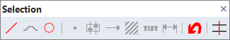
Example of 2D toolbar available for selection of single objects, and additional option icons
For a list of all functions and commands, see List of All VariCAD Functions.
For a list of all hotkeys, see Hotkeys
Creating, Opening and Saving VariCAD 2D/3D Files
Create a New File – DOP, Ctrl + N |
VariCAD always starts with a new, empty file. This file has the default file parameters, and is assigned a preliminary name of “NONAME” plus new file’s serial number (for instance NONAME 1). In order to save this file, you must assign a valid filename. If you want to create another new file, you can confirm or change its parameters. Defined parameters of new file are:
- Units - choose between inches or millimeters. If you change these units later, existing 2D dimensions will not change.
- Drawing format - choose layouts such as A, B, C, A4, A3, A2, etc. You can also define a custom format, and the format can be changed at any time. The drawing format is relevant when printing, if you select “Print according to format,” and for the Zoom Drawing Format tool. In addition, the 2D sheet border is created according to the selected format. In 3D, the format is only used for the initial dimensions of 3D space projection.
- Drawing scale - used only for 2D drawing. Dimensions, arrows, texts and other annotations are created according to the defined scale. The scale can be changed at any time, but be aware that this will change the existing annotation objects.
VariCAD file contains both 3D part and 2D part. Settings of a new file attributes are mostly related to 2D part. If you open a new file, you do not define assembly, sub-assembly or part file status. These attributes can be created later, according to assembly or part definitions.
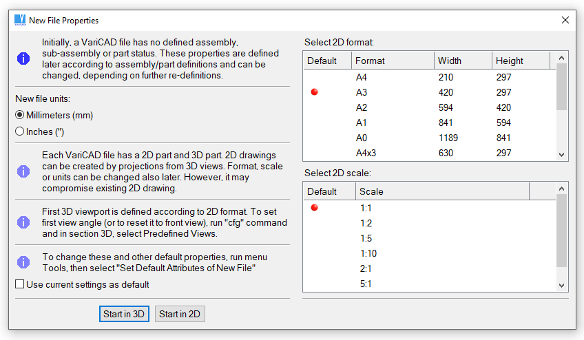
New file creation window
Current File Attributes as Default - DEF |
This function enables you to set the defaults for all new files. The dialog is similar to the creation of a new file (see the previous function).
The mode (3D/2D), units (millimeters or inches), sheet border format, scale and 2D grid distance can be defined in a window. Predefined 2D layers, 2D default line attributes (current layer, color and line style) and predefined angles of the construction lines are copied from the current file.
Open an Existing File – DAD, Ctrl + O |
Opens an existing file. You can also open an existing file by pressing Tab, if the previous function is finished and “Ready” is displayed in the Status Bar.
Open Recent Files |
This function allows you to open a file from the list of recently used files rather than from the standard file dialog.
Reopen the current document - REOPEN |
Opens again the current document. If there are any changes, you are prompted before they are discarded. This commend can be used for instance, if you make changes and if you want to start again differently.
Close – CLO, Ctrl + F4 |
Closes the current file. Next current file is the file which was active previously. If only one file is open, you are asked whether to exit the session or to create another new file with the default parameters.
Saving and Inserting 2D/3D Files
Save – DSV, Ctrl + S |
Saves the current file. If the file was created as new or copied to new document window, you must define a valid filename.
Save As – SVA |
Saves the current file. You can select a different filename or different file type, like STEP, DWG etc.
Save Only Selected Objects - DPS |
Select objects first. Then define a filename. You can save selected objects to any other supported file type.
Insert Objects from File - DPO |
Inserts all objects from the selected file to the current file. If you are in 2D, only 2D objects are inserted. If you are in 3D, only 3D objects are inserted.
Selection of 2D objects is described at Selecting, 2D Objects. Selection of 3D solids is described at Selecting Solids. 2D objects from another file are inserted similarly as 2D blocks – see Insert Block. 3D objects from another file are inserted the same way as the solids are transformed and copied – see Transforming and Copying Solids.
Open/Save Dialog and Recent Files Dialog
“Open an existing file” dialog panel and “Open recent files” dialog panel contains also a file preview. Moving cursor over list of files, the preview displays highlighted item information:
- Content image (for folders only if they are defined).
- Assembly status or folder prompt.
- Title (if defined).
- Description (if defined).
Both panels can be switched between each other. Apart from opening of previously used files, Recent files dialog allows you also to open files from folder the highlighted item belongs to. Such an option is available from right-click.
Recent files dialog is also accessible from File save dialog (command “Save as”). In this case, you can select a recently used file – it will be rewritten. Or, select a folder. The file to be saved is saved into corresponding folder (directory).
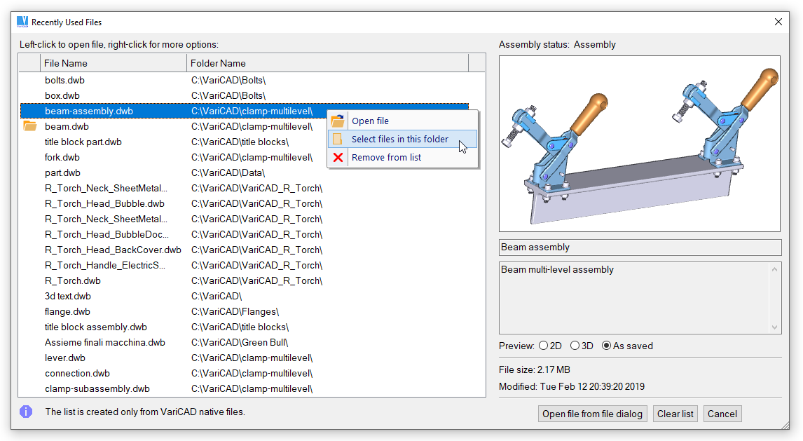
Recent files dialog, right-click options
File or Folder Preview Definition
While saved, a file stores also bitmap image which is later displayed in file dialog preview. You have multiple possibilities to define how a preview image is created.
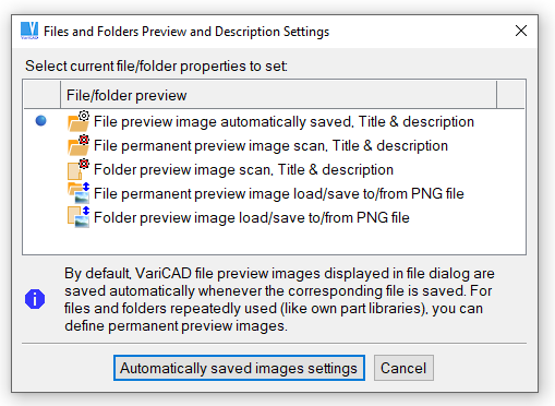
Files or folders preview settings
File/Folder Preview Definition - FDP |
Following options are:
| File preview is created automatically |
File preview image is saved automatically, whenever a file is saved. The image content is the file 3D part. Here, you can define whether the image is created from currently used angle of view, or from predefined view (like front view, top view, user defined view…). File title and detailed description can be defined, too.
| File preview image is permanent |
Contrary to previous option, the image remains the same, independent on current file content. This option is useful especially for repeatedly inserted solids, if they are not changed anymore. The image defined here is scanned from display, under selected view and optionally, using enhanced rendering. File title and detailed description can be defined, too.
| Folder preview image |
You can define preview image also for current folder. The method is the same as for permanent file preview image definition. Also, folder title and detailed description can be defined. Folder preview data are stored in file type *.dwb_fpv. Filename is the folder name, the file is located in the parent folder (one level up, where the corresponding folder belongs to).
| File preview permanent image load/save |
If a permanent file preview image is defined, you can save it into PNG format. Then, you can edit the image outside VariCAD and load it back. Or, you can load PNG image completely created outside VariCAD (for example, a logo). It is necessary to save/load a pair of images. Images dimensions are 400x250 and 800x500. The larger is used for 4k resolution.
| Folder preview image load/save |
This option is the same as described above. Images are used for folder preview.
Automatically saved images settings
For automatically saved previews, you can select whether a current zoom is used or “Zoom all” is preferred. Also, one color for entire solid vs. multiple colors (if used) can be selected. In settings described above, angle of view is defined, but not zoom vs. entire view. Settings above are related for each file or folder individually, settings here are used for all files.
VariCAD files created in versions up to 2018 do not contain preview images or titles and descriptions. Previews are displayed only as wire-framed 3D scene.
Backing up Your Files
Backup saves 2D/3D files after a specified number of changes. If the session ends unintentionally, you can recover your backup data the next time you use VariCAD. To turn safety backups on/off, run “CFG” command.
Working with Multiple Files
Changing Active File
To change the current (active) file, you can always use pull-down menu “Windows” and select the file to be active from the list. The list of open files is limited to 10 items. If the number of open files is greater, use the following function instead:
Windows – WIN, Ctrl + 3 |
This function offers you a clearly arranged list of the open files. You can save or close any selected file or activate selected file from the list.
Previous Document Window – SWD, Ctrl + TAB |
Activates a previously active file. Repeatedly used, this function allows you to easily switch between the two files.
Save All Changed – SVALL |
Saves all changed open files to VariCAD native format. If the file is created as new or copied to a new document window, you must always define its real name. If the file is imported from another format, you must confirm or redefine the file name. If the current files are all from the native format, no dialog is displayed.
New Document from Current Document - NDW |
Creates a new file, copies all objects from the current file and activates this file.
You can set working with multiple files from command “CFG”. Available options are:
- Whether the last open files are open automatically in the next session startup
- How the 2D objects are inserted from another file
- How the 2D objects are inserted from clipboard
Copy and Paste
VariCAD works with separate clipboards for 2D objects and for 3D objects. During work with VariCAD, you can store objects to a corresponding clipboard and whenever insert them to any open file.
Copy – CPY, Ctrl + C |
Stores selected objects to the clipboard.
Paste – PAS, Ctrl + V |
Insert objects from the clipboard to the current file.
Cut – to Clipboard – CCUT, Ctrl + X |
Cut (delete) and put objects to clipboard (Copy)
Switching between 2D and 3D
Switch to 2D - 2D, Alt + 2 |
Switch to 3D - 3D, Alt + 3 |
You can switch between 2D and 3D at any time. To switch, you can:
- Click the 2D or 3D icon
- Use hotkey Alt + 2 to switch to 2D, and Alt + 3 to switch to 3D.
Switching between 2D and 3D also changes the available toolbars and menus. There is no direct link between 2D and 3D data, but you can update 2D views after making changes in 3D by using 3D View Exports.
Sketching - 2D Drawing in 3D Planes, Alt + S |
Sketching is used for creation of contours, later extruded, rotated or lofted into 3D space. Sketching is used also for editing of those contours of existing solids. To start sketching of new contours, click axes displayed in lower left corner of VariCAD 3D window. See Sketching.
Undo and Redo
Undo – UND, Ctrl + Z |
Redo – RED, Ctrl + Y |
When creating 2D or 3D data, you can use Undo to return backward step-by-step to previous states of your 2D/3D objects. You can also return to where you began work, or to the point at which the file was loaded. Once Undo has been used, Redo can be used to step forward. Undo/Redo history is separate for 2D and 3D objects. When working with assembly connections, this history is lost after parts are reloaded into the assembly after changes have been made. If this occurs, you will receive a message informing you of the problem.
Dragging Objects
Many 2D functions and some methods of 3D transformation use dragging. In command “CFG”, you can choose between two methods of dragging. In both methods, the cursor defines the position of the reference point or insertion point.
- Dragging without clicking - position change is defined by cursor movement. If the cursor approaches snap points (such as endpoints), the reference point will “stick” to this point until the cursor is moved by at least half the aperture size. Left click ends the dragging movement.
- Clicking and dragging - objects are moved while the left button is pressed. If this button is not pressed, you can define any location simply by clicking on it. Right click or pressing Enter ends the dragging movement. This option is not recommended – it is obsolete (legacy) option.
Dragging Increments
Dragging increments can be always set or turned off during objects dragging. To do so, right-click mouse button. Select dragging increment from menu. Also, you can select input of exact location from keyboard.
Dragging increments are defined as fixed length increments. However, you may also select dragging increments changed according to zoom. In such case, the larger zoom is, the smaller increment is used.
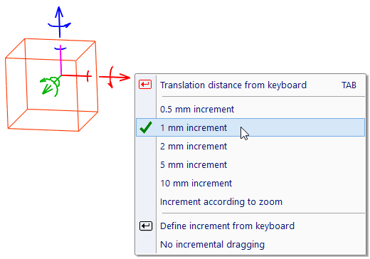
Example of dragging increments settings, in 3D transformation
Turning off Detection Temporarily
Objects are detected by cursor automatically. If you drag selected objects and if you move cursor over other 2D lines or 3D solids, location is changed according to detection. In 3D dragging, objects may jump unexpectedly, because the detected location is projected to dragging vector. In 2D or in 3D, you may need to select a location regardless the other objects. If dragging increment is used, an exact distance is obtained by cursor movement.
Automatic objects detection can be temporarily turned off by following methods:
- Press and hold F1 while moving cursor. This turns detection off only for dragging.
- Hold left-mouse button pressed, Then, dragging is finished when you release the button. Again, this turns detection off only for dragging.
- Press and hold F2 while moving cursor. This turns detection off always – not only for 2D or 3D location, but also for detection of any objects.
Run command “CFG” if you need to manage how detection is temporarily disabled.